


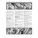

Starter motor brushes
(later models) - renewal #
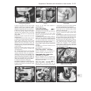
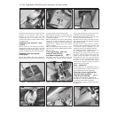
25 When renewing the starter motor brushes
on later models, the old brushes will need to
be crushed (in a vice or with a hammer) and
their leads then soldered to the new brushes.
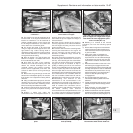
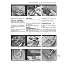
Fuses - later models
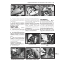
26 The fuse arrangement is slightly different
on later models, but the circuits protected are
still identified by a symbol. Refer to the
Specifications Section for full details. Note
also the terminal block with plastic cover,
which can be used to isolate the battery from
the electrical system by disconnecting the
leads from the terminals (photos).
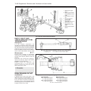
Relays (Turbo ie models) -
general
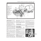
27 On Turbo ie models, the relays mounted
in the fuse block are as shown in Fig. 13.103.
Additional relays are located as follows:
Headlamp relay - on lead under main fuse
block
Fuel injection system main control relay -
adjacent to airflow meter
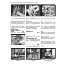
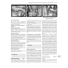
Headlamps later models
28 The headlamp units fitted on later models
differ according to model, but the bulb and
unit replacement details are generally the
same as described for previous models in
Chapter 9. Note that the rubber cover can
only be fitted with the tab to the top as shown
(photo).
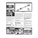
Headlamp beam adjusters for
load compensation - later
models
29 Some later models are fitted with
headlamp beam adjusters which allow
temporary resetting to be made (such as
when the car is fully loaded). Access to these
adjusters is made by lifting the bonnet (photo).
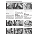
30 Turn the adjusters anti-clockwise to lower
the beam to the normal level or clockwise to
raise the beam (when the car is unloaded).
Repeat the procedure on the opposite
headlamp unit an equal amount.
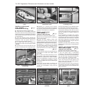
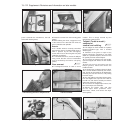
31 Other later models have separate
horizontal and vertical beam adjusters,
positioned as shown (photos). A load
compensating lever is attached to the
adjusters to enable temporary resetting of the
headlamp beams, without changing the
normal adjustment. Turn the lever to the
appropriate side (right or left) to make the
adjustment as required. The normal setting
Supplement: Revisions and information on later models 13•105
15.26B Battery lead terminal block on the
1301 cc Turbo ie model
15.23B Starter motor and wiring
connections on the 1372 cc ie engine
15.31B Headlamp vertical beam alignment
adjuster screw on a 1372 cc ie model. Note
the load compensator lever which is set in
the “O” (normal load) setting position
15.31A Headlamp horizontal beam
alignment adjuster screw on a 1372 cc ie
model
15.29 Headlamp beam adjuster on the
999 cc Turbo ie model
15.28 Headlamp unit fitted to the 1372 cc ie
model
15.26A Fuse block on the 1301 cc Turbo ie
model
13
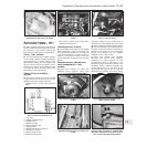
Fig. 13.103 Auxiliary fuses and relays on
1301 cc Turbo ie models (Sec 15)
1 Horn relay
2 Heated rear screen relay
3 Foglamps relay
4 Radiator fan relay
5 Electric windows relay
6 Foglamps fuse
7 Radiator fan second speed fuse
8 Fuel injector fan fuse
9 Electric windows fuse
10 Electric fuel pump fuse