


balljoint from the hub carrier using a suitable
“splitter” tool. If such a tool is not available,
support the base of the brake disc and drive
the balljoint taper pin downwards, but screw
on the nut to protect the threads.
4 Remove the hub carrier.
5 Refitting is a reversal of removal, use a new
driveshaft nut and tighten all nuts and bolts to
the specified torque. Stake the driveshaft nut
after tightening.
6 Track control arm -
removal and refitting
3
1 Raise the front of the car and support it
securely.
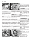
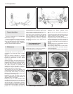
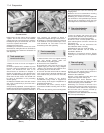
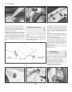
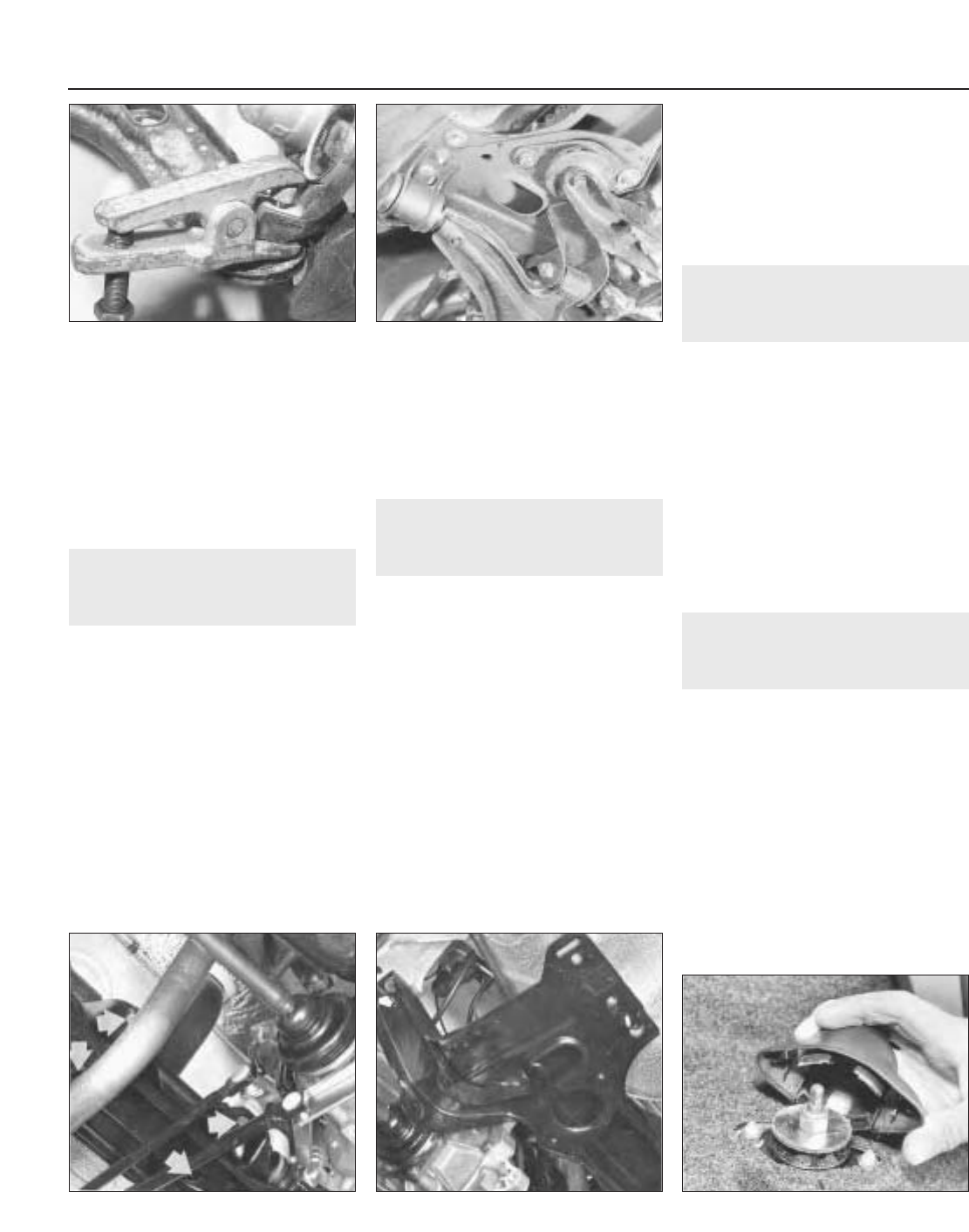
2 Unless a special tool is available to press
the track control arm balljoint from the hub
carrier, the driveshaft will have to be
disconnected as described in Chapter 7,
Section 2, paragraphs 1 to 8 to provide more
space to enable the balljoint taper pin to be
driven from the hub carrier. This should now
be done as described in the preceding
Section (photo).
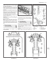
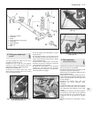
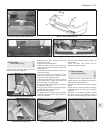
3 Unbolt the inboard end of the track control
arm. This is retained by a pivot bolt and a
clamp (photo).
4 As previously explained, a worn balljoint or
flexible pivot bushes will necessitate renewal
of the track control arm complete. Note that it
may, however, be possible to obtain a
replacement balljoint through a motor factor.
5 Refitting is a reversal of removal. Tighten all
nuts and bolts to the specified torque. Use a
new driveshaft nut and stake it into the
driveshaft groove after tightening.
7 Front crossmember -
removal and refitting
3
1 Raise the front of the car, support securely
with axle stands placed under the
side-members or sill jacking points.
2 Remove the front roadwheels.
3 Unscrew the nuts from the tie-rod end
balljoint taper pins and then using a balljoint
“splitter” tool disconnect the balljoints from
the steering arms on the hub carrier.
4 Unscrew the bolts which hold the inboard
track control arms to the body members, and
also withdraw the pivot bolt from the body
bracket.
5 Support the weight of the engine/
transmission using a hoist or support bar
across the top of the engine compartment as
described in Chapter 6.
6 Disconnect the lower (central) engine/
transmission flexible mounting from the floor
pan.
7 Unscrew the steering rack mounting bolts
and remove them. Leave the steering rack
hanging loose.
8 Remove the front crossmember mounting
bolts and manoeuvre it from the car.
9 Refitting is a reversal of removal. Tighten all
nuts and bolts to the specified torque wrench
settings and on completion, check the front
wheel alignment as described in Chapter 10.
8 Rear shock absorber -
removal and refitting
3
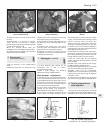
1 Open the tailgate and remove the cover
from the shock absorber top mounting which
is located within the luggage area (photo).
2 Hold the flats on the spindle with an
open-ended spanner and then unscrew the
self-locking nut.
3 Working under the car, disconnect the
shock absorber lower mounting.
4 Withdraw the unit from under the wing.
5 The shock absorber can be tested as
described in Section 2.
6 Refitting is a reversal of removal. Tighten
mounting nuts and bolts to the specified
torque.
9 Rear coil spring -
removal and refitting
3
1 Raise the rear of the car and support it
securely on axle stands placed under the
side-members or sill jacking points.
2 Remove the roadwheel.
3 Place a jack under the brake drum and
support the suspension trailing arm.
4 Disconnect the shock absorber lower
mounting and then lower the trailing arm jack
until the coil spring can be withdrawn.
5 Refitting is a reversal of removal. If the
spring is being changed, make sure that it is
of the same colour code as the original and
that its lower coil is correctly located up
against its stop in the spring pan.
6 Tighten the shock absorber lower mounting
bolt to the specified torque.
11•4 Suspension
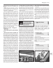
8.1 Rear shock absorber upper mounting
cover
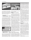
Fig. 11.7 Front crossmember bolts (Sec 7)Fig. 11.6 Steering rack mounting bolts
(Sec 7)
6.3 Track control arm inboard fixing6.2 Separating track control arm balljoint
from hub carrier