


13•88 Supplement: Revisions and information on later models
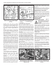
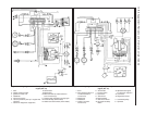
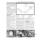
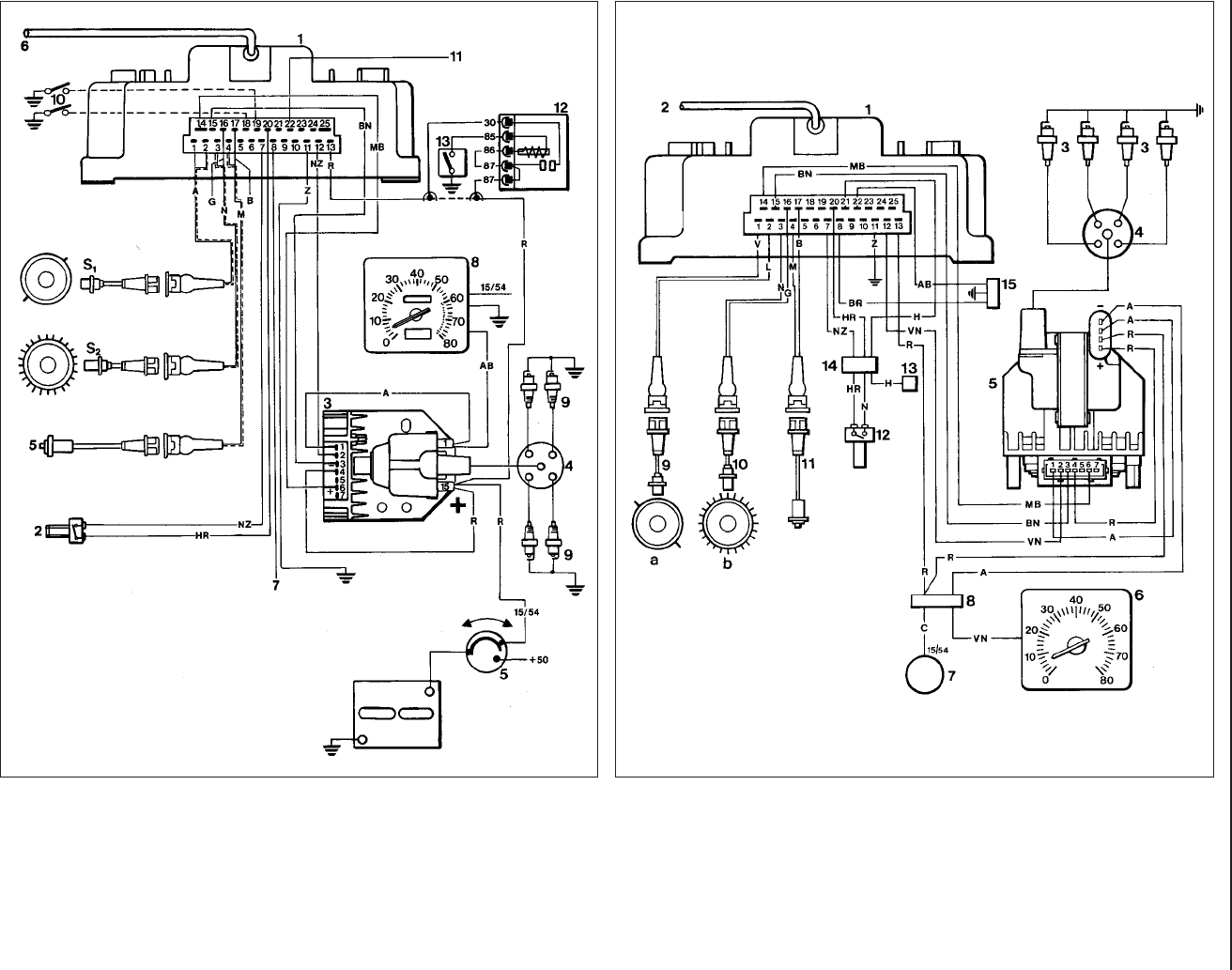
Fig. 13.73 Wiring diagram of the Microplex ignition system on the 1301 cc Turbo ie
engine (Sec 10)
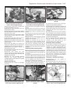
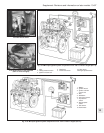
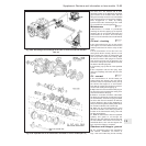
Fig. 13.74 Wiring diagram of the Microplex ignition system on the 1372 cc Turbo ie
engine (Sec 10)
1 ECU
2 Safety pressure switch
3 Ignition unit with coil
4 Distributor
5 Anti-knock sensor
6 Vacuum/pressure pick-up in engine inlet
manifold
7 Socket for diagnostic equipment
8 Tachometer
9 Spark plugs
10 Switch to earth (to retard advance
curve if necessary)
11 Turbocharger operation warning light
12 Anti-theft relay (where fitted)
13 Hidden anti-theft switch (where fitted)
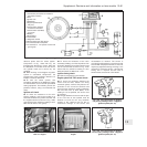
1 ECU
2 Pipe (pressure/vacuum
in inlet manifold to
control unit)
3 Spark plug
4 Distributor
5 Ignition coil (with
control unit)
6 Tachometer
7 Ignition switch
8 Connector
9 TDC sensor
10 Engine speed
11 Anti-knock sensor
12 Air pressure safety
switch
13 Speedometer signal
for electronic injection
14 Connector
15 Diagnostic socket
a Crankshaft pulley
b Flywheel