


Vacuum servo unit and master
cylinder - general
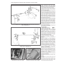
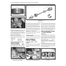
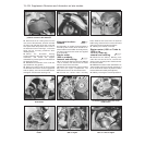
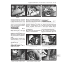
54 Access to the vacuum servo unit and the
master cylinder can only be obtained after the
cooling system expansion tank has been
released and moved aside (photo).
Antiskid system - description
55 This system is available as an option on
the Turbo ie models only.
56 The purpose of the system is to prevent
the wheel(s) locking during heavy brake
applications. This is achieved by automatic
release of the brake on a roadwheel which is
about to lock up, after which the brake is
re-applied. This cycle is carried out many
times per second under heavy braking,
retaining full steering control to avoid any
hazards.
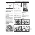
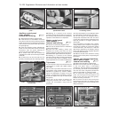
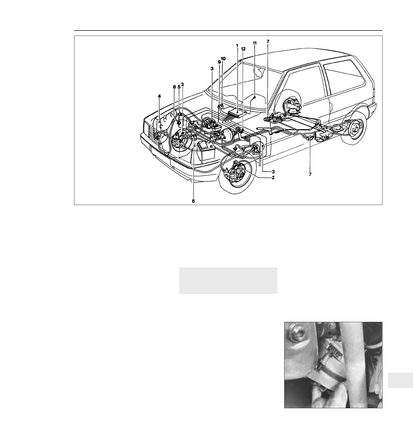
57 The main components of the system are
shown in Fig. 13.102. The control module
processes the signals received from the
sensors, and compares them with
deceleration values of the roadwheel and the
slip values of the tyre, which are stored in the
module memory.
58 When reference values are exceeded and
wheel lock is imminent, the control module
signals the pressure modulators, which in turn
decrease the brake hydraulic pressure.
59 Vehicle road speeds are also taken into
account by the module’s electronic circuits.
60 In order to retain optimum system
performance, the tyres and wheels should
always be of the type originally fitted by the
vehicle manufacturer.
61 Maintenance of the system should be
limited to checking the security of all electrical
and hydraulic connections. Individual compo-
nents are not repairable, and must be
renewed complete if faulty.
15 Electrical system
Alternator (999 and
1108 cc models) -
removal and refitting ¡
1 To remove the alternator from 999 cc
engine models, disconnect the leads from the
terminals on its rear face.
2 Extract the screws and remove the plastic
drivebelt guard.
3 Slacken the mounting and adjuster bolts,
push the alternator in towards the engine and
remove the drivebelt.
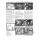
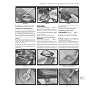
4 Remove the mounting and adjuster bolts,
and withdraw the alternator downwards
through the gap between the right-hand
driveshaft and the engine sump pan (photo).
5 Refitting is a reversal of removal; re-tension
the drivebelt.
Alternator (later models) -
removal and refitting ¡
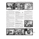
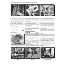
6 Disconnect the battery negative lead.
7 Loosen off the right-hand front roadwheel
bolts, then raise and support the car at the
front end on axle stands. Remove the
right-hand roadwheel.
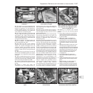
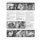
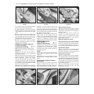
8 Remove the wheel arch underwing shield
by driving the compression pins from the
centre of the retaining clips (using a 2 mm
drift), then prise free the panel retaining clips
and remove the shield. Keep the pins and
clips in a safe place and renew any that may
have been damaged during removal (photo).
9 Detach the wiring connector from the
alternator.
10 Release the alternator mounting and belt
adjuster link bolts, and take off the drivebelt.
11 Take out the alternator top and bottom
mounting bolts.
Supplement: Revisions and information on later models 13•103
15.4 Removing the alternator from the
999 cc engine
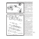
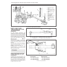
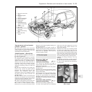
Fig. 13.102 Braking system on Turbo ie Antiskid models (Sec 14)
13
1 Electronic control unit
(ECU)
2 Roadwheel speed
sensors
3 Pressure modulators
4 Vacuum reservoir
5 Check valve
6 Air cleaner
7 Load proportioning
(pressure regulating)
valves
8 Vacuum switch
9 ECU relay
10 System fault warning
lamp relay
11 System fault warning
lamp
12 Brake stop lamp
switch