


28 Loosen off the retaining clips and detach
the air intake pipe from the air filter.
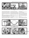
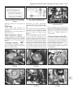
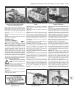
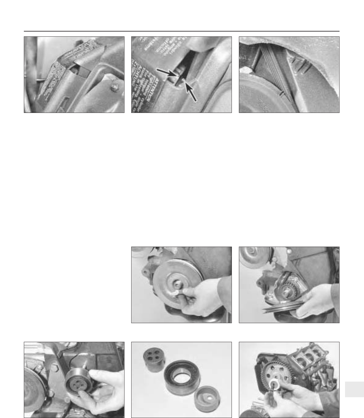
29 Slide back the inspection cover from the
upper end of the timing cover (photo).
30 Turn the engine over by hand to bring the
TDC timing marks of the flywheel-
to-bellhousing and the camshaft sprocket
-to-rear cover projection into alignment. The
crankshaft pulley also has a TDC timing mark
and this should be positioned as shown
(photos).
31 Loosen off the retaining and adjustment
strap fixings, then pivot the alternator towards
the engine.
32 Unscrew the upper retaining bolts
securing the timing cover.
33 Loosen off the nut securing the alternator
and its drivebelt relay, then detach and
remove the alternator drivebelt.
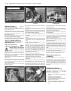
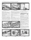
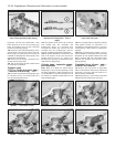
34 Unscrew and remove the crankshaft
pulley nut. Where the engine is in the car,
prevent the crankshaft from turning by
engaging top gear and having an assistant
apply the brake pedal hard. Unscrew and
remove the flywheel housing lower cover bolts
and remove the cover. The flywheel ring gear
can now be jammed with a suitable lever or
implement to prevent the crankshaft from
rotating. It should be noted that the pulley nut
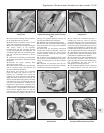
is tightened to a considerable torque and a
strong socket, together with an L-bar and
extension tube, will therefore be required to
loosen and remove it (photo). Take care not to
damage the gearbox/flywheel housing by
jamming the flywheel at a weak point.
35 Withdraw the crankshaft pulley (photo).
36 Unscrew and remove the lower retaining
bolts and remove the timing cover upwards
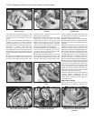
from the vehicle.
37 Check that the previously mentioned
timing marks are still in alignment. Loosen off
the timing belt tensioner nut, then with the
tension released, withdraw the timing belt
from the sprockets.
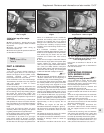
38 To remove the drivebelt tensioner, undo
the securing nut and withdraw the tensioner
pulley unit noting that it is in three sections
(photos).
39 If desired, the sprockets and the rear
timing belt cover can be removed as follows,
otherwise proceed to paragraph 49.
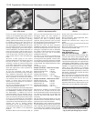
40 To remove the camshaft sprocket, a
suitable tool must be used to hold the
camshaft stationary as the sprocket bolt is
loosened. A suitable tool can be improvised
as shown in photo 7B.48 using two pieces of
steel bar joined together by a pivot bolt, with
suitable bolts through the ends of the steel
bars to engage with the holes in the sprocket.
41 Unscrew the sprocket bolt, then recover
the plain washer, and the thrust washer which
is bonded into a plastic sleeve (photo).
42 The sprocket can now be withdrawn from
the end of the camshaft. If the sprocket is
tight, carefully lever it from the camshaft using
two screwdrivers, but take care not to
damage the rear timing belt cover.
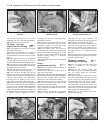
43 The crankshaft sprocket can be removed
by simply pulling it from the end of the
Supplement: Revisions and information on later models 13•39
7B.30B Crankshaft pulley and timing cover
timing marks
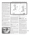
7B.30A Camshaft sprocket timing notch
aligned with timing (TDC) pointer in timing
case
7B.29 Slide back inspection cover in the
timing case
7B.41 Removing the crankshaft sprocket
bolt, plain washer and thrust washer
7B.38B The three sections of the timing
belt tensioner
7B.35 Crankshaft pulley removal7B.34 Crankshaft pulley nut removal
7B.38A Timing belt tensioner removal
13