


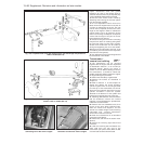
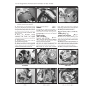
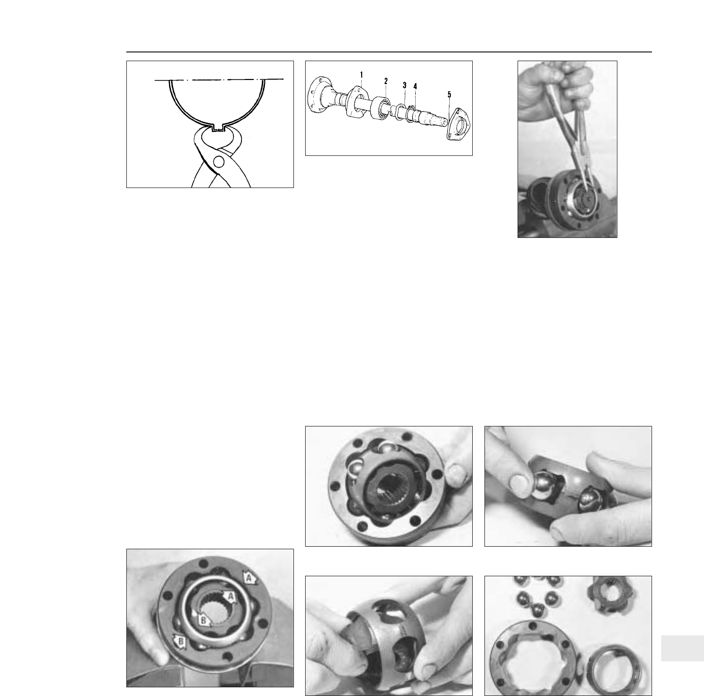
3 The boot retaining band must be crimped
using suitable pinchers at the highest point on
the boot.
Intermediate driveshaft
(Turbo ie models) #
Description
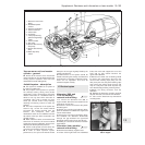
4 On these models, an intermediate
driveshaft is fitted between the final drive of
the transmission and the flange of the
right-hand driveshaft.
5 A support bearing assembly for the
intermediate shaft is bolted to the engine
crankcase. The bearing carrier also acts as
the alternator bracket.
Removal
6 Drain the transmission oil. Disconnect the
right-hand driveshaft from the intermediate
shaft flange, move the driveshaft aside, and
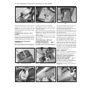
support it.
7 Unscrew and remove the bolts which hold
the intermediate shaft retainer plate to the
crankcase support bracket.
8 Withdraw the intermediate shaft from the
final drive housing. The shaft assembly,
complete with bearing, will pass through the
crankcase support bracket until the bearing
retainer and flexible boot can be slipped off
the shaft.
Bearing renewal
9 The bearing on the intermediate shaft can
be renewed after removing the plate, circlip
and washer, and pressing the shaft out of the
bearing.
10 When fitting the new bearing, apply
pressure only to the inner track, and do not
apply any heat.
Refitting
11 This is a reversal of removal. Tighten all
bolts to the specified torque and replenish the
transmission oil.
Inboard CV joints (Turbo
ie models) - overhaul #
12 A worn joint is best renewed, but it may
be necessary to dismantle it for cleaning, if
replacement of a split boot has been
neglected.
13 Disconnect the boot securing clip and pull
the boot up the shaft. Wipe away the old
grease.
14 Extract the joint securing circlip and pull
the joint from the shaft.
15 Renew the joint complete if it is worn or
damaged.
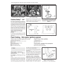
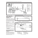
16 Before dismantling the joint, align the
housing and ball cage marks “A” and “B”
(Fig. 13.100).
17 Tap the joint from its backplate.
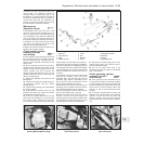
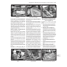
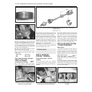
18 Turn the ball/cage assembly through 90º,
mark its relative position to the outer track
and withdraw it (photo).
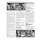
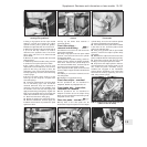
19 The balls are a light snap fit in the cage.
Once they are removed, the inner and outer
cage members can be separated; again, mark
the side of the cages in relation to the outer
track (photos).
Supplement: Revisions and information on later models 13•99
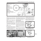
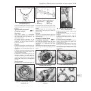
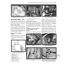
Fig. 13.99 Extracting the CV joint circlip -
Turbo ie models (Sec 13)
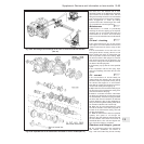
Fig. 13.98 Components of the intermediate
driveshaft - Turbo ie models (Sec 13)
1 Bearing retaining
plate
2 Ball bearing
3 Wave washer
4 Circlip
5 Bearing cap
Fig. 13.97 Crimping the driveshaft boot
securing band (Sec 13)
13.19C Components of CV joint13.19B Separating inner and outer cage
members
13.19A CV joint balls and cage13.18 Removing inboard CV joint ball/cage
assembly from outer track
Fig. 13.100 CV joint housing and ball cage
alignment marks (A and B) - Turbo ie
models (Sec 13)
13