optimum engine operating efficiency. In the
event of a system sensor malfunction, errors
in data passed to the ECU are overcome by
an emergency operation, whereby the ECU
supplies the injectors with one of two set
injection periods independent of the sensors.
One period (2.2 ms) is for idle speed and the
other (2.5 ms) is for speeds above idle
(actuated when the idle speed contact is
opened).
4 An injection system relay and a fuel pump
relay are fitted and are located in the engine
compartment, adjacent to the ECU on the left-
hand inner wing panel. In the event of the
engine not being started within two seconds of
the ignition being switched to the “ON”
position, the fuel pump relay is deactivated.
The fuel pump circuit fuse is located in the
main fuse block located under the facia within
the car. Note: To avoid possible damage to the
ECU, it is essential that the ignition is switched
off before disconnecting (or connecting) the
wiring multi-plug from the ECU. A Lambda (or
oxygen) sensor is fitted to L3.2 equipped
models, to measure exhaust gas oxygen
content. In sending signals to the ECU,
optimum catalyst operation is maintained.
Fuel system -
depressurisation ¡
5 The fuel system should always be
depressurised whenever any fuel hoses
and/or system components are disconnected
and/or removed. This can easily be achieved
as follows.
6 The fuel pump relay is located next to the
ECU and airflow meter in the engine
compartment. Carefully pull free the fuel
pump relay, then start the engine and run it
until it stops. The fuel system is now
depressurised. Turn the ignition off before
removing/dismantling any components.
7 Do not refit the fuel pump relay or turn the
ignition on until the system is fully
reconnected. When the engine is ready to be
restarted, refit the relay and its cover, then
restart the engine in the normal manner.
Maintenance ¡
8 Regularly check the condition and security
of the system hoses and connections. Also
check the system wiring connections for
condition and security.
9 At the specified intervals, renew the air
cleaner element and the fuel filter.
Fuel filter - renewal ¡
10 This is located in the engine compartment
on the right-hand side. Disconnect the fuel
inlet and outlet hoses, but be prepared for the
loss of fuel. Loosen off the clamp and remove
the filter.
11 Reverse the removal procedure to fit the
new filter, but ensure that the arrow indicating
fuel flow is pointing towards the fuel injector rail.
Air cleaner element -
renewal ¡
12 Prise free the four retaining clips, then
remove the cover and the air cleaner element.
13 Wipe clean the inside surfaces of the air
cleaner housing, then insert the new element,
refit the cover and secure it with the four
retaining clips.
Checks and adjustments ∞
Engine idle speed and mixture
adjustment
14 Before carrying out any adjustments, the
engine must be at its normal operating
temperature, the cooling fan having cut into
Supplement: Revisions and information on later models 13•79
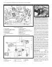
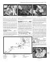
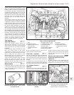
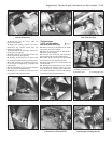
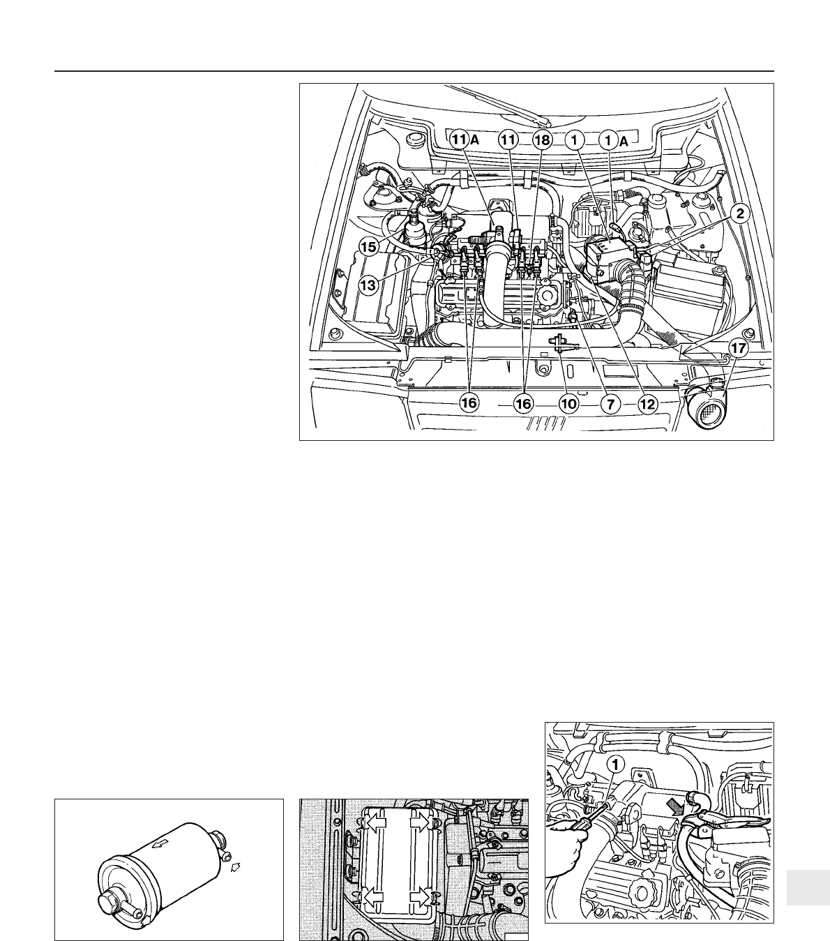
Fig. 13.49 Fuel injection system components layout in engine compartment on the
1372 cc Turbo ie engine (Sec 9E)
1 ECU
1A Diagnostic socket
2 Ignition system relay and
fuel pump relay
7 Coolant temperature
sensor
10 Supplementary air valve
11 Throttle position switch
11A Throttle housing
12 Airflow meter
13 Fuel pressure regulator
15 Secondary fuel filter
16 Injectors
17 Injector cooling fan
18 Thermostatic switch (to
engage injector cooling
fan)
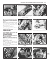
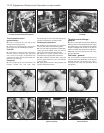
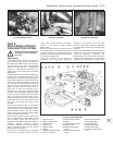
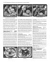
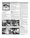
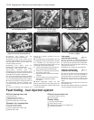
Fig. 13.52 Idle speed adjustment screw (1)
on the 1372 cc Turbo ie engine (Sec 9E)
Note method of compressing the
supplementary air valve pipe (arrowed)
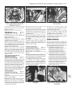
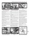
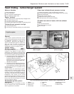
Fig. 13.51 Air cleaner cover securing clips
(arrowed) on the 1372 cc Turbo ie engine
(Sec 9E)
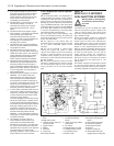
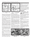
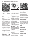
Fig. 13.50 Secondary fuel filter with arrows
indicating direction of flow - 1372 cc Turbo
ie engine (Sec 9E)
13


