


into its cylinder to accommodate them. This
will cause the fluid level to rise in the reservoir.
Anticipate this by syphoning some out
beforehand, but take care not to let it drip
onto the paintwork - it acts as an effective
paint stripperl
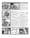
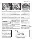
8 Refit the anti-rattle springs, the pads
(friction lining-to-disc), the cylinder body, the
locking blocks and their retaining clips
(photos).
9 Refit the roadwheel and apply the footbrake
hard, several times, to bring the pads into
contact with the brake disc.
10 Renew the pads on the opposite brake.
The pads should always be renewed in axle
sets.
11 Top up the fluid reservoir.
4 Rear brake shoes -
inspection and renewal
2
1 Jack up the rear of the car and remove the
roadwheels.
2 Fully release the handbrake.
3 Unscrew and remove the drum securing
bolts. One of these is a long locating spigot
for the roadwheel.
4 Pull off the drum. lf it is tight, clean off the
rust at its joint with the hub flange, and apply
a little penetrating fluid. Two bolts may be
screwed into the drum securing bolt holes if
necessary and the drum thus eased off the
hub. The securing bolt holes are tapped for
this purpose.
5 Brush away all the dust and dirt from the
shoes and operating mechanism, taking care
not to inhale it.
6 The friction linings fitted as original
equipment are of the bonded type and the
rivet heads normally used as a guide to wear
are not, of course, fitted. However, if the
thickness of the friction linings is down to
1.5 mm (0.06 in) or less, the shoes must be
renewed. Always purchase new or factory
relined brake shoes.
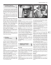
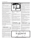
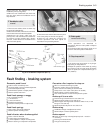
7 Before removing the brake shoes, note the
way in which the shoes are positioned, with
respect to leading and trailing ends (the end
of the shoe not covered by lining material).
Note also into which holes in the shoe web
the return springs are connected. Sketch the
shoes or mark the holes on the new shoes
with quick drying paint if you are doubtful
about remembering (photo).
8 Undo the steady springs by depressing and
rotating their caps a quarter turn to disengage
the slot from the pin. On later models a
U-shaped steady spring is used. Depress and
slide it out.
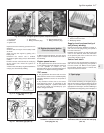
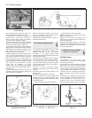
9 Rotate the hub until the cut-outs in its rear
flange face are in alignment with the shoe
self-adjusters.
10 Pivot the trailing shoe on the self-adjuster
post and disengage the ends of the shoe from
the slot in the wheel cylinder tappet and from
the lower anchor block.
11 Work the shoe up the self-adjuster pivot
post until the self-adjuster boss enters the
cut-out in the hub flange. The shoe can now
be withdrawn (photo).
12 Once off the self-adjuster post, the
pull-off spring tension is eased, as the shoe
can move towards the other, so the springs
can be unhooked.
13 Remove the leading shoe in a similar way.
14 The new shoes will already be fitted with
new self-adjusters.
15 Fit the new shoes to their self-adjuster
posts, making sure that the handbrake shoe
lever is correctly located. Engage the ends of
the shoes.
16 Using a wooden or plastic-faced mallet,
tap the shoes inwards against the friction of
their self-adjuster coil springs. This will have
the effect of reducing the overall diameter of
the shoes to facilitate fitting of the shoe return
springs and to allow the brake drum to slide
over them.
17 Using pliers, reconnect the upper (longer)
and lower shoe return springs.
18 Hold the steady pins in position from the
rear of the backplate. Fit the small coil springs
and the retaining cap, again using pliers to
grip the cap and to depress and turn it to
engage the pin. On later models fit the
U-shaped springs.
19 Before refitting the drum, clean it out and
examine it for grooves or scoring (refer to
Section 8).
20 Fit the drum and the roadwheel.
21 Apply the brakes two or three times to
position the shoes close to the drum.
22 Renew the shoes on the opposite brake in
a similar way.
23 The handbrake should be automatically
adjusted by the action of the shoe adjuster. If
the handbrake control lever has excessive
travel, refer to Section 16 for separate
adjusting instructions.
5 Caliper - removal,
overhaul and refitting
4
Note: Purchase a repair kit in advance of
overhaul.
1 Jack up the front roadwheel and remove it.
2 Brush away all dirt from the caliper
Braking system 8•3
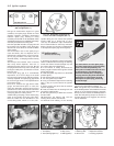
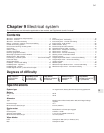
4.11 Rear hub showing cut-outs on rear
face for shoe self-adjuster bosses
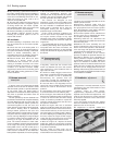
4.7 Rear brake assembly3.8B Cylinder body located on caliper
bracket
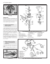
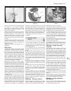
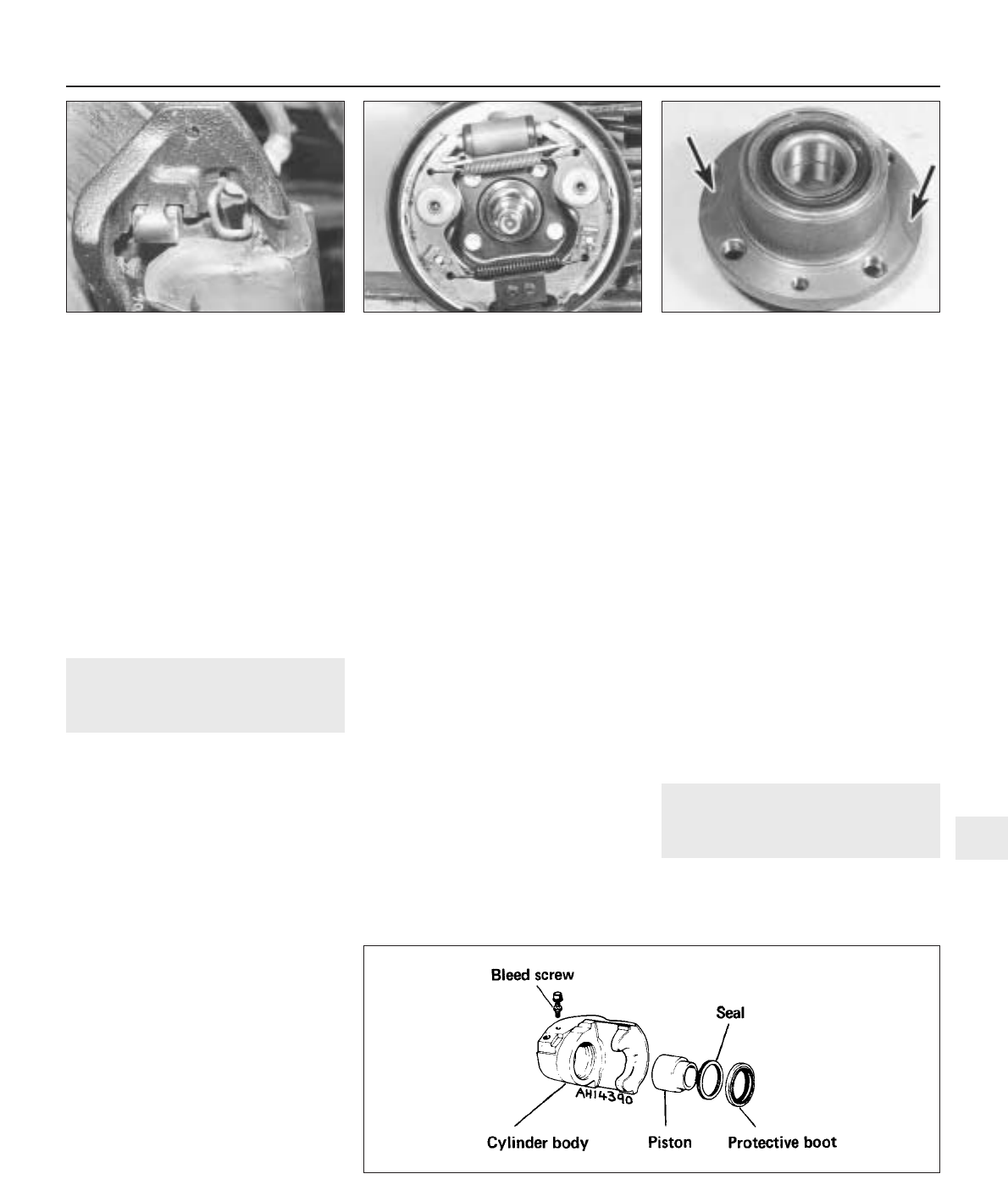
Fig. 8.2 Exploded view of caliper (Sec 5)
8