


657 Actuator (30-70 and 87)
Instruction Manual
Form 1900
February 2007
9
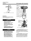
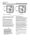
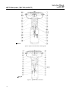
Actuator Disassembly
1. Bypass the control valve. Reduce the loading
pressure to atmospheric, and remove the tubing or
piping from the upper diaphragm casing (key 1).
WARNING
To avoid personal injury from the
precompressed spring force thrusting
the upper diaphragm casing (key 1)
away from the actuator, relieve spring
compression (step 2, below), and
carefully remove casing cap screws
(key 22) (step 4, below).
2. Thread the spring adjuster (key 12) out of the
yoke (key 9) until all spring compression is relieved.
3. If required, remove the actuator from the valve
body by separating the stem connector (key 26) and
removing the yoke locknut or, for the size 87
actuator, the stud bolt nuts. Separate the stem
connector by loosening the stem nuts (keys 15
and 16) and unscrewing the two cap screws.
4. Remove the diaphragm casing cap screws and
nuts (keys 22 and 23), then lift off the upper
diaphragm casing (key 1).
5. Remove the actuator diaphragm (key 2).
6. Remove the diaphragm plate, actuator stem, and
cap screw (keys 4, 10 and 3) as an assembly. This
assembly can be broken down further, if required, by
removing the cap screw (key 3).
7. Remove the actuator spring (key 6) and the
spring seat (key 11).
8. If required, remove the lower diaphragm casing
(key 5) from the yoke (key 9) by loosening the cap
screws (key 8) that hold it in place.
9. If required, remove the spring adjuster (key 12)
by unscrewing it from the yoke (key 9).
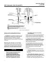
Actuator Assembly
1. Coat the threads and the spring seat bearing
surface of the spring adjuster (key 12) with lithium
grease (key 241), and thread the spring adjuster into
the yoke (key 9). Place the spring seat (key 11) in
the yoke on the spring adjuster and turn the spring
adjuster to ensure that threads are properly
engaged.
2. Position the lower diaphragm casing (key 5) on
the yoke (key 9), and fasten the parts together by
installing and evenly tightening the cap screws
(key 8).
3. Set the actuator spring (key 6) squarely onto the
spring seat (key 11).
4. If the diaphragm plate and actuator stem (keys 4
and 10) are separate, fasten them together using the
cap screw and washer (keys 3 and 25). Coat the cap
screw threads with lithium grease (key 241). Tighten
the cap screw (key 3) to 41 NSm (30 lbfSft) torque for
size 30 actuators, 54 NSm (40 lbfSft) torque for
size 34 and 40 actuators, or 149 NSm (110 lbfSft)
torque for size 45 to 87 actuators. Slide the actuator
stem and diaphragm plate (keys 10 and 4) into the
yoke (key 9) so that the actuator spring (key 6) fits
squarely between the diaphragm plate and the
spring seat (key 11). Then slide the diaphragm rod
through the spring adjuster (key 12).
5. Place the diaphragm (key 2) pattern-side up on
the diaphragm plate (key 4). Align the holes in the
diaphragm and the lower diaphragm casing (key 5).
6. Position the upper diaphragm casing (key 1) on
the diaphragm (key 2) and align the holes.
Note
When you replace actuator
diaphragms in the field, take care to
ensure the diaphragm casing bolts are
tightened to the proper load to prevent
leakage, but not crush the material.
Perform the following tightening
sequence with a manual torque
wrench for size 30-70 and 87 actuators.
CAUTION
Over-tightening the diaphragm casing
cap screws and nuts (keys 22 and 23)
can damage the diaphragm. Do not
exceed 27 NSm (20 lbfSft) torque.
Note
Do not use lubricant on these bolts
and nuts. Fasteners must be clean and
dry.
7. Insert the cap screws (key 22), and tighten the
hex nuts (key 23) in the following manner. The first
four hex nuts tightened should be diametrically
opposed and 90 degrees apart. Tighten these four
hex nuts to 13 NSm (10 lbfSft).