


657 Actuator (30-70 and 87)
Instruction Manual
Form 1900
February 2007
6
nameplate. Apply loading pressure to the
diaphragm.
CAUTION
Stroke the actuator a few times to
ensure that the pressure gauge is
working correctly, and that the
actuator is functioning properly. To
prevent product damage, it is
important to be sure that the actuator
assembly is not
binding or producing
any loading friction on the actuator
stem movement.
1. If not already accomplished, provide a temporary
means of applying an adjustable loading pressure to
the actuator during bench set adjustments.
2. Set the diaphragm loading pressure at 0 psig.
Then, slowly raise the pressure from 0 psig towards
the lower bench set pressure while checking for the
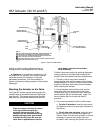
first movement of the actuator stem. The actuator
stem should show movement at the lower bench set
pressure. If movement occurs before or after the
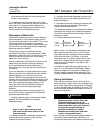
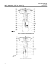
lower pressure is reached, adjust the spring adjuster
(see figure 4) into or out of the yoke until the
actuator stem’s movement is first detected at the
lower bench set pressure.
3. Be sure the spring adjuster is adjusted to meet
the requirements of step 2 above.
4. Apply the upper bench set loading pressure to
the diaphragm. This pressure extends the actuator
stem down towards the valve. (Note: the actuator
stem may slide over the valve stem as shown in
figure 4.) At the end of the actuator stem, use a
marker or a piece of tape to mark the valve stem
(see figure 4). (Note: If the actuator stem does not
pass over the valve stem, provide a method to mark
this point of stem travel.).
5. Slowly decrease the diaphragm loading pressure
until the lower bench set pressure is applied.
Measure the distance between the marker or tape
on the valve stem to the end of the actuator stem.
The distance should match the travel span shown on
the travel indicator scale (key 18). If the span of
travel is correct, bench set is complete. Proceed to
the Installing the Stem Connector Assembly
subsection.
6. If the travel span is not correct, a wrong or
damaged spring has been installed in the actuator.
To obtain the correct spring sizing information, refer
to Catalog 14, Actuator Sizing and Sample
Calculation sections to determine the correct spring
selection for your application. Or, contact your
Emerson Process Management sales office for
assistance. After replacing the spring, repeat the
steps above.
Installing the Stem Connector
Assembly
When installing the stem connector assembly
(key 26), the actuator and valve stem threads should
engage the threads of the stem connector by the
distance of the diameter of the stem.
Note
Replacement stem connectors are an
assembly of two stem connector
halves, cap screws, and a spacer
between the connector halves.
Remove the spacer and discard, if
present, before clamping the actuator
and valve stems together.
1. If necessary, push the valve stem down so that it
is touching the seat ring on direct acting valves. For
reverse acting valves, push the stem down to the
open position.
If necessary, screw the valve stem locknuts down,
away from the connector location. For all actuators
except size 87, ensure that the travel indicator disk
(key 14) is located on top of the locknuts.
2. Slowly increase the diaphragm pressure to the
upper bench set pressure. This should be the same
pressure used in the bench set steps, and it is
marked on the nameplate.
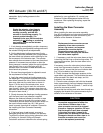
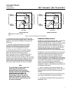
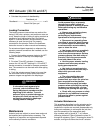
3. Place the stem connector half with the threaded
holes, approximately half way between the actuator
and valve stems. Refer to figures 6, 7, and 8 to help
locate the connector position.
Be sure that the actuator and valve stem threads are
engaging the threads of the stem connector by the
distance of one diameter of the stem.
CAUTION
Incomplete engagement of either the
valve stem or actuator stem in the
stem connector can result in stripped
threads or improper operation. Be sure
that the length of each stem clamped
in the stem connector is equal to or
greater than one diameter of that stem.
Damage to threads on either stem or in
the stem connector can cause the
parts to be replaced prematurely.