


657 Actuator (30-70 and 87)
Instruction Manual
Form 1900
February 2007
4
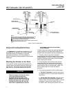
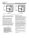
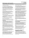
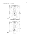
Figure 4. Bench Set Adjustment
SPRING ADJUSTER
LOWER BENCH SET
LOADING PRESSURE
UPPER BENCH SET
PRESSURE MARK
VALVE
STEM
RATED VALVE
TRAVEL MEASURE
MARK VALVE
STEM HERE
UPPER BENCH SET
LOADING PRESSURE
ACTUATOR
STEM
NOTES:
THE LOWER PSIG LOADING PRESSURE (MARKED ON NAMEPLATE)
WHERE THE FIRST MOVEMENT OF ACTUATOR STEM IS DETECTED.
THE UPPER PSIG LOADING PRESSURE EXTEND ACTUATOR STEM.
MARK THIS POINT WITH TAPE OR A MARKER.
MEASURE DISTANCE OF TRAVEL. IT SHOULD EQUAL THE TRAVEL SPAN
SHOWN ON THE TRAVEL INDICATOR SCALE.
2
3
1
3
4
40A8715–B
B2426 / IL
1
2
3
4
section to confirm that the adjustment has not
changed since it was shipped from the factory.
D Positioner: If a positioner is installed, or is to
be installed on the actuator, refer to the positioner
instruction manual for installation. During the
adjustment procedures, it will be necessary to
provide a temporary loading pressure to the actuator
diaphragm.
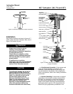
Mounting the Actuator on the Valve
The Type 657 actuator spring loading pushes the
actuator stem up towards the actuator diaphragm
(see figure 2). This spring action moves the stem
away from the valve while installing the actuator.
CAUTION
If the valve stem is allowed to remain
in the up position (towards the
actuator) during mounting, it can
interfere with the actuator mounting,
possibly damage valve stem threads
or bend the valve stem. Be sure the
valve stem is pushed down (into the
valve body), away from the actuator
while mounting.
Provide a temporary method of applying diaphragm
loading pressure to the diaphragm to extend the
actuator stem during bench set spring adjustments.
1. Provide a vise or some other method of
supporting the valve and the weight of the actuator
during assembly. For direct or reverse acting valves,
push the valve stem down away from the actuator
while mounting the actuator.
2. Screw the stem locknuts all the way onto the
valve stem. With the concave side of the travel
indicator disk (key 14) facing the valve, install the
travel indicator disk on the valve stem. (Note: The
travel indicator disk is not used with size 87
actuators.)
3. Lift or hoist the actuator onto the valve bonnet:
a. For size 87 actuators, insert the cap screws
and tighten the hex nuts, securing the actuator to
the bonnet.
b. For all other size actuators, screw the yoke
locknut onto the valve bonnet and tighten the
locknut. (Note: On small size actuators, it may be
necessary to remove the indicator disk and
re-install it while lowering the actuator on to the