


657 Actuator (30-70 and 87)
Instruction Manual
Form 1900
February 2007
7
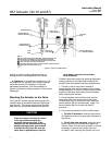
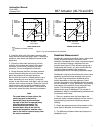
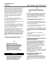
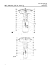
Figure 5. Typical Valve Response to Deadband
UPPER
BENCH SET
PRESSURE
LOWER
BENCH SET
PRESSURE
9
3
0
CLOSING
VALVE
15
1.0
0.6
0.2
OPENING
VALVE
OPEN
CLOSED
MID RANGE
VALVE TRAVEL
DIAPHRAGM PRESSURE, PSIG
DIAPHRAGM PRESSURE, BAR
RANGE OF
DEADBAND
1
UPPER
BENCH SET
PRESSURE
LOWER
BENCH SET
PRESSURE
9
3
0
CLOSING
VALVE
15
1.0
0.6
0.2
OPENING
VALVE
OPEN
CLOSED
MID RANGE
VALVE TRAVEL
DIAPHRAGM PRESSURE, PSIG
DIAPHRAGM PRESSURE, BAR
1
NOTE:
DEADBAND IS CAUSED BY FRICTION.
A6763-2 / IL
RANGE OF
DEADBAND
1
DIRECT ACTING VALVE REVERSE ACTING VALVE
4. Install the other half of the stem connector and
insert the cap screws and tighten them. If installing a
positioner, also attach the feedback bracket at the
same time.
5. Screw the valve stem locknuts up until the
indicator disk contacts the bottom of the stem
connector, or for size 87 actuators, the stem
connector. Do not overtighten the locknuts.
6. Slowly decrease and then increase pressure
several times stroking the valve from the lower
bench set pressure to the upper pressure.
Be sure that the valve is in closed position (up or
down, depending on valve action). Loosen the
screws on the travel scale, and align it with the travel
indicator disk or stem connector. Stroke the valve full
travel to ensure that the travel matches the valve
travel on the travel indicator plate. If valve travel is
not correct, repeat the stem connector procedure.
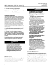
Note
For push-down-to-close valves, the
valve plug seat is the limit for
downward travel and the actuator
up-stop is the limit for upward (away
from the valve) movement. For
push-down-to-open valves, the
actuator down stop is the limit for
downward movement, and the valve
seat is the limit for upward (away from
the valve) movement.
Deadband Measurement
Deadband is caused by packing friction, unbalanced
forces, and other factors in the control valve
assembly. Deadband is the range a measured signal
can vary without initiating a response from the
actuator (see figure 5). Each actuator spring has a
fixed spring rate (force). You have verified that the
right spring was installed in the actuator by
completing the Bench Set Spring Adjustment steps.
Deadband is one factor that affects the control valve
assembly operation during automatic loop control.
The control loop tolerance for deadband varies
widely depending on the loop response. Some
common symptoms of the deadband being too wide
are no movement, a “jump” movement, or oscillating
movements of the actuator during automatic loop
control. The following steps are provided to
determine the span of deadband. The percent of
deadband is helpful in troubleshooting problems with
the process control loop.
1. Start at a pressure near the lower bench set
pressure, slowly increase pressure until the valve is
approximately at mid-travel. Note this pressure
reading.
2. Slowly decrease pressure until movement of the
valve stem is detected, and note this pressure.
3. The difference between these two pressures is
deadband, in psi.