


657 Actuator (30-70 and 87)
Instruction Manual
Form 1900
February 2007
10
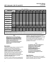
8. Tighten the remaining hex nuts in a clockwise,
criss-cross pattern to 13 NSm (10 lbfSft).
9. Repeat this procedure by tightening four hex
nuts, diametrically opposed and 90 degrees apart, to
a torque of 27 NSm (20 lbfSft).
10. Tighten the remaining hex nuts in a clockwise,
criss-cross pattern to 27 NSm (20 lbfSft).
11. After the last hex nut is tightened to 27 NSm (20
lbfSft), all of the hex nuts should be tightened again
to 27 NSm (20 lbfSft) in a circular pattern around the
bolt circle.
12. Once completed, no more tightening is
recommended.
13. Mount the actuator on the valve by following the
procedures in the Installation section.
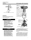
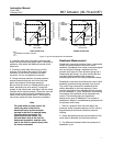
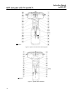
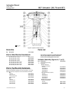
Top-Mounted Handwheel Assembly
A top-mounted handwheel assembly (figures 9
and 10) is usually used as an adjustable
casing-mounted up travel stop to limit full retraction
of the actuator stem. Turning the handwheel
clockwise moves the the handwheel stem (key 133,
figures 9 and 10) down, compressing the spring.
Instructions are given below for complete
disassembly and assembly of the top-mounted
handwheel assembly. Perform the disassembly only
as far as necessary to accomplish the required
maintenance; then, begin the assembly at the
appropriate step.
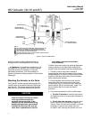
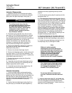
Key numbers refer to figure 9 (sizes 30 through 60)
and figure 10 (sizes 70 and 87), unless otherwise
indicated.
Disassembly for Top-Mounted
Handwheel
1. Turn the handwheel (key 51) counter-clockwise
so that the handwheel assembly is not causing any
spring compression.
2. Bypass the control valve, reduce loading
pressure to atmospheric, and remove the tubing or
piping from the upper handjack body (key 142,
figures 9 or 10).
WARNING
To avoid personal injury from the
precompressed spring force thrusting
the upper diaphragm casing (key 1)
away from the actuator, thread the
spring adjuster (key 12) out of the
yoke until all spring compression is
relieved, then carefully remove casing
cap screws (key 22).
3. Remove the diaphragm casing cap screws and
nuts (keys 22 and 23, figures 6, 7, or 8), and lift off
the upper diaphragm casing and handwheel
assembly.
4. If necessary, the handwheel assembly can be
separated from the diaphragm casing by removing
the cap screws (key 141). This may be necessary to
replace the O-ring (key 139), or for ease of handling.
5. Loosen the travel stop locknut (key 137), and turn
the handwheel (key 51) counter-clockwise. Remove
the cotter pin and stop nut (keys 247 and 54), then
lift off the handwheel.
6. Unscrew the travel stop locknut (key 137) from
the handwheel stem (key 133), and turn the stem out
of the bottom of the body (key 142). A screwdriver
slot is provided on the top of the stem for this
purpose.
7. Replace the O-ring (key 138) in the body
(key 142).
8. For a handwheel assembly used on sizes 30
through 60 actuators, complete the disassembly by
driving out the groove pin (key 140, figure 9) and
sliding the pusher plate (key 135, figure 9) off the
stem.
For a handwheel assembly used on a sizes 70
or 87 actuator, complete the disassembly by
unscrewing the retaining screw (key 174, figure 10)
and removing the thrust bearing and pusher plate
(keys 175 and 135, figure 10). Because the retaining
screw (key 174) has left-hand threads, turn
clockwise to loosen.
Assembly for Top-Mounted Handwheel
1. For a handwheel assembly used on sizes 30
through 60 actuators, coat the end of the
handwheel stem (key 133, figure 9) with anti-seize
lubricant (key 244). Slide the pusher plate (key 135,
figure 9), onto the stem, and drive in the groove pin
(key 140, figure 9) to lock the pieces together.
For a handwheel assembly used on a sizes 70
or 87 actuator, pack the thrust bearing (key 175,