


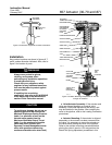

657 Actuator (30-70 and 87)
Instruction Manual
Form 1900
February 2007
11
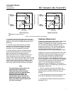
figure 10) with anti-seize lubricant (key 244). Place
the thrust bearing in the pusher plate (key 135,
figure 10), slide the two parts onto the handwheel
stem (key 133). Coat the retaining screw threads
with thread locking sealant (key 242). Insert and
tighten the retaining screw (key 174, figure 10).
2. Coat the O-ring (key 138) with lithium grease
(key 241), and insert the O-ring in the body
(key 142).
3. Coat the threads of the handwheel stem
(key 133) with anti-seize lubricant (key 244). Screw
the stem into the body (key 142).
4. Thread the travel stop locknut (key 137) onto the
handwheel stem (key 133).
5. Place the handwheel (key 51), and the stop nut
(key 54) on the handwheel stem (key 133). Tighten
the hex nut to fasten the parts together. Secure the
nut with the cotter pin (key 247).
6. If the body (key 142) was separated from the
upper diaphragm casing (key 1, figures 6, 7, or 8),
lubricate the O-ring (key 139) with lithium grease
(key 241), and place the O-ring in the body. Align the
holes in the diaphragm casing and the body, insert
the cap screws (key 141), and tighten them evenly
following a crisscross pattern to ensure a proper
seal.
7. Position the upper diaphragm casing (key 1) on
the diaphragm (key 2) and align the holes.
Note
When you replace actuator
diaphragms in the field, take care to
ensure the diaphragm casing bolts are
tightened to the proper load to prevent
leakage, but not crush the material.
Perform the following tightening
sequence with a manual torque
wrench for size 30-70 and 87 actuators.
CAUTION
Over-tightening the diaphragm casing
cap screws and nuts (keys 22 and 23)
can damage the diaphragm. Do not
exceed 27 NSm (20 lbfSft) torque.
Note
Do not use lubricant on these bolts
and nuts. Fasteners must be clean and
dry.
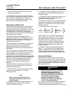
8. Insert the cap screws (key 22), and tighten the
hex nuts (key 23) in the following manner. The first
four hex nuts tightened should be diametrically
opposed and 90 degrees apart. Tighten these four
hex nuts to 13 NSm (10 lbfSft).
9. Tighten the remaining hex nuts in a clockwise,
criss-cross pattern to 13 NSm (10 lbfSft).
10. Repeat this procedure by tightening four hex
nuts, diametrically opposed and 90 degrees apart, to
a torque of 27 NSm (20 lbfSft).
11. Tighten the remaining hex nuts in a clockwise,
criss-cross pattern to 27 NSm (20 lbfSft).
12. After the last hex nut is tightened to 27 NSm (20
lbfSft), all of the hex nuts should be tightened again
to 27 NSm (20 lbfSft) in a circular pattern around the
bolt circle.
13. Once completed, no more tightening is
recommended.
14. Mount the actuator on the valve following the
procedures in the Installation section.
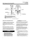
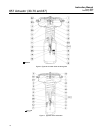
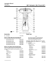
Side-Mounted Handwheel for Sizes 34
through 60 Actuators
A side-mounted handwheel assembly (figures 11
and 12) is normally used as a manual actuator for
sizes 34 through 60 actuators. Turning the
handwheel counter-clockwise past the neutral
position opens the valve. Two levers (key 146,
figure 11) on a handwheel assembly operate the
valve by moving the valve stem.
Instructions are given below for complete
disassembly and assembly. Perform the
disassembly only as far as necessary to accomplish
the required maintenance; then begin the assembly
at the appropriate step.
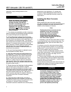
Disassembly for Side-Mounted
Handwheel (Size 34-60)
1. If desired, the handwheel assembly can be
removed from the actuator yoke. To do this, remove
the hex nuts (keys 147 and 170) from the U-bolts
(keys 166 and 143) that hold the assembly to the
yoke.