


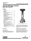

657 Actuator (30-70 and 87)
Instruction Manual
Form 1900
February 2007
5
valve because the disk will not go through the
actuator yoke opening).
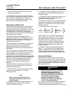
4. Do not connect the actuator stem to the valve
stem at this time. Whenever the actuator is installed
on the valve, it is recommended to perform the
Bench Set Spring Adjustment procedure to verify
that the actuator is still adjusted correctly.
Discussion of Bench Set
The bench set pressure range is used to adjust the
initial compression of the actuator spring with the
valve-actuator assembly “on the bench.” The correct
initial compression is important for the proper
functioning of the valve-actuator assembly when it is
put into service and the proper actuator diaphragm
operating pressure is applied.
The bench set range is established with the
assumption that there is no packing friction. When
attempting to adjust the spring in the field, it is very
difficult to ensure that there is no friction being
applied by “loose” packing.
Accurate adjustment to the bench set range can be
made during the actuator mounting process by
making the adjustment before the actuator is
connected to the valve (see the Spring Verification
Procedure).
If you are attempting to adjust the bench set range
after the actuator is connected to the valve and the
packing tightened, you must take friction into
account. Make the spring adjustment such that full
actuator travel occurs at the bench set range (a) plus
the friction force divided by the effective diaphragm
area with increasing diaphragm pressure or (b)
minus the friction force divided by the effective
diaphragm area with decreasing diaphragm
pressure.
For an assembled valve-actuator assembly, the
valve friction may be determined by following the
procedure described below:
1. Install a pressure gauge in the actuator loading
pressure line that connects to the actuator
diaphragm casing.
Note
Steps 2 and 4 require that you read
and record the pressure shown on the
pressure gauge.
2. Increase the actuator diaphragm pressure and
read the diaphragm pressure as the actuator
reaches its mid-travel position.
3. Increase the actuator diaphragm pressure until
the actuator is at a travel position greater than its
mid-travel position.
4. Decrease the actuator diaphragm pressure and
read the diaphragm pressure as the actuator
reaches its mid-travel position.
The difference between the two diaphragm pressure
readings is the change in the diaphragm pressure
required to overcome the friction forces in the two
directions of travel.
5. Calculate the actual friction force:
Friction
Force, = 0.5
pounds
Difference
in pressure
readings, psig
Effective
diaphragm area,
inches
2
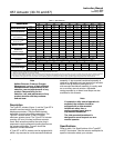
Refer to table 1 for the effective diaphragm area.
When determining valve friction, you can make
diaphragm pressure readings at a travel position
other than mid-travel if you desire. If you take
readings at zero or at the full travel position, take
extra care to ensure that the readings are taken
when the travel just begins or just stops at the
position selected.
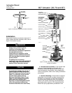
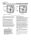
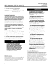
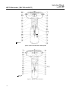
It is difficult to rotate the spring adjustor (key 12,
figure 6, 7, and 8) when the full actuator loading
pressure is applied to the actuator. Release the
actuator loading pressure before adjusting. Then
re-apply loading pressure to check the adjustment.
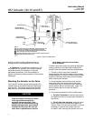
Spring Verification
Ensure that the actuator stem is at the top of its
travel as shown in figure 4 and not connected to the
valve. (Note: Some spring compression is required
to move the diaphragm to the top of its travel.) The
bench set steps provided are the same for direct or
reverse acting valves.
WARNING
When moving the actuator stem with
diaphragm loading pressure, use
caution to keep hands and tools out of
the actuator stem travel path. Personal
injury and/or property damage is
possible if something is caught
between the actuator stem and other
control valve assembly parts.
Also, provide a certified pressure gauge suitable to
accurately read the diaphragm pressure from 0
through the upper bench set pressure marked on the