


657 Actuator (30-70 and 87)
Instruction Manual
Form 1900
February 2007
12
2. Remove the retaining ring (key 154) and drive out
the lever pivot pin (key 153).
3. Two screws (key 156) hold the right- and
left-hand levers (key 146) together. Remove the
screw from the top of the levers so that the levers
will drop down out of the assembly. Disassemble
further, if necessary, by removing the other screw.
4. Remove the screw (key 161) and pointer
mounting bolt (key 159, not shown) located behind
pointer (key 160).
5. Remove the stop nut (key 54), lockwasher
(key 150), and washer (key 149). Then remove the
handwheel (key 51), being careful not to lose the
small ball (key 55) and spring (key 56).
6. Loosen the locking set screw (key 168, not
shown). Then, using a suitable tool, unscrew the
bearing retainer (key 136).
7. Pull the handwheel screw assembly (key 145) out
of the handwheel body. The operating nut (key 132)
will come out with the screw. Also remove the
bushing (key 151).
8. If required, remove the two ball bearings
(key 152), one from the bearing retainer and the
other from the handwheel body.
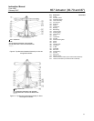
Assembly for Side-Mounted Handwheel
(Size 34-60)
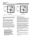
1. Pack the ball bearings (key 152) with anti-seize
lubricant (key 244). Insert one bearing and the
bushing (key 151) into the handwheel body
(key 142) as shown in figure 11 or 12. The bushing
is not used in a handwheel assembly for sizes 45
through 60 actuators.
2. Coat the handwheel screw assembly (key 145)
threads with anti-seize lubricant (key 244), and
thread the operating nut (key 132) onto the screw.
Slide the second ball bearing (key 152) onto the
screw, and insert the end of the screw into either the
bushing (key 151), as shown in figure 11, or into the
bearing.
3. Thread the bearing retainer (key 136) into the
body (key 142). Completely tighten the bearing
retainer, and then loosen it one-quarter turn. Tighten
the set screw (key 168, not shown) to hold the
bearing retainer in place.
4. Coat the groove in the handwheel body (key 142)
with lithium grease (key 241). Insert the spring
(key 56) and ball (key 55) into the handwheel
(key 51). Holding the ball and spring in the
handwheel, put the handwheel, the washer
(key 149), the lockwasher (key 150), and the stop
nut (key 54) onto the end of the handwheel screw
(key 145). Tighten the stop nut.
5. Position the pointer mounting bolt (key 159, not
shown) and pointer (key 160) as shown in figure 11
or 12. Insert and tighten the screw (key 161).
6. Assemble the two levers (key 146) with the cap
screws (key 156) for handwheel assemblies for
sizes 45, 50, and 60 actuators, or with the machine
screws (key 156) for handwheel assemblies on
sizes 34 and 40 actuators.
7. If the handwheel assembly was removed from the
yoke (key 9, figures 6, 7, or 8), remount the handjack
assembly to the yoke using the dowel pins for
alignment. Position the U-bolts (keys 166 and 143)
on the yoke, and hand-tighten the hex nuts
(keys 170 and 147) to hold the handwheel assembly
in position. Cap screws (key 163) should be tight
against the yoke legs to provide stability. Tighten
nuts (key 144). Finish tightening the U-bolt nuts
to 163 NSm [120 lbfSft] (key 170) and 41 NSm [30
lbfSft] (key 147). Be sure the handwheel assembly
remains flat against the mounting pad and
perpendicular to the yoke.
8. Position the levers (key 146) as shown in
figure 11 or 12. Insert the lever pivot pin (key 153),
and snap the retaining ring (key 154) onto the lever
pivot pin.
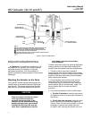
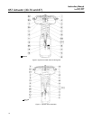
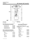
Side-Mounted Handwheel for Sizes 70
and 87 Actuators
A side-mounted handwheel assembly (figure 13) is
normally used as a manual actuator for sizes 70
and 87 actuators. Turning the handwheel
counter-clockwise past the neutral position opens
the valve body. A pair of sleeves (keys 34 and 46,
figure 13) operates the valve by moving the valve
stem.
Instructions are given below for complete
disassembly and assembly. Perform the
disassembly only as far as necessary to accomplish
the required maintenance; and then begin the
assembly at the appropriate step.
Key numbers refer to figures 7 or 8, and 11.
Disassembly for Side-Mounted
Handwheel (Size 70 & 87)
1. Bypass the control valve, reduce loading
pressure to atmospheric, and remove the tubing or
piping from the upper diaphragm casing (key 1).
2. Remove cover band (key 60), and relieve spring
compression by turning the spring adjuster (key 12)
counter-clockwise.