


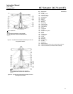
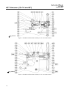
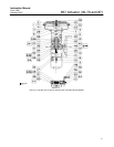
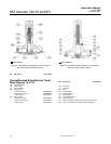

657 Actuator (30-70 and 87)
Instruction Manual
Form 1900
February 2007
15
Disassembly for Casing-Mounted Travel
Stop
1. Bypass the control valve. Reduce the loading
pressure to atmospheric, and remove the tubing or
piping from the connection in the body (key 142).
WARNING
To avoid personal injury from the
precompressed spring force thrusting
the upper diaphragm casing (key 1)
away from the actuator, relieve spring
compression (steps 2 and 3, below),
and carefully remove casing cap
screws (key 22) (step 4, below).
2. Thread the spring adjuster (key 12) out of the
yoke (key 9) until all spring compression is relieved.
Casing-Mounted Adjustable Up Travel Stops
1. Remove the travel stop cap (key 187) and loosen
the travel stop nut (key 137). Rotate the travel stop
stem (key 133) counter-clockwise until the travel
stop assembly is no longer compressing the spring.
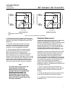
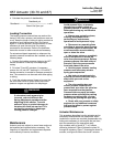
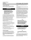
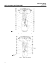
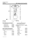
2. Remove the upper diaphragm casing (key 1,
figures 6, 7, or 8) as outlined in the Maintenance
section.
3. Remove the cap screws (keys 141) and separate
the travel stop assembly from the upper casing.
4. Remove and inspect the O-rings (keys 138
and 139); replace if necessary.
5. For sizes 30 through 60, drive out the groove
pin (key 140), and slide the pusher plate (key 135)
off the travel stop stem (key 133).
For sizes 70 and 87, remove the retaining screw
(key 174) to inspect the thrust bearing (key 175).
Casing-Mounted Adjustable Down Travel Stops
1. Remove the travel stop cap (key 187). Unscrew
the jam nut and stop nut (keys 189 and 54) until the
travel stop assembly is no longer compressing the
spring. Remove the jam nut and stop nut.
2. Remove the upper diaphragm casing (key 1,
figures 6, 7, or 8) as outlined in the Maintenance
section.
3. Remove the cap screws (keys 141) and
separate the travel stop assembly from the upper
casing.
4. Remove and inspect the O-ring (keys 139);
replace if necessary.
5. Loosen the stop nut (key 54), then unscrew the
travel stop stem (key 133) out of the actuator stem.
The lower diaphragm plate can now be removed.
Assembly for Casing-Mounted Travel
Stop
1. Reassemble the up or down travel stop in the
reverse order of the disassembly steps, being sure
to apply lubricant as shown by the lubrication boxes
(key 241) in figures 6, 7, 8, 14, 15, or 16, as
appropriate.
2. Readjust the travel stop to obtain the appropriate
restriction by following the adjustment procedures
presented in the introductory portion of the
Casing-Mounted Adjustable Travel Stops section.
Return the unit to operation.
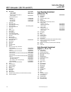
Parts Ordering
Each actuator has a serial number stamped on the
nameplate. Always mention this number when
corresponding with your Emerson Process
Management sales office regarding technical
information or replacement parts. Also, reference the
complete 11-character part number of each needed
part as found in the following Parts List.
WARNING
Use only genuine Fisherr replacement
parts. Components that are not
supplied by Emerson Process
Management should not, under any
circumstances, be used in any Fisher
valve, because they will void your
warranty, might adversely affect the
performance of the valve, and could
give rise to personal injury and
property damage.
Note
Neither Emerson, Emerson Process
Management, nor any of their affiliated
entities assumes responsibility for the
selection, use and maintenance of any
product. Responsibility for the
selection, use, and maintenance of any
product remains with the purchaser
and end-user.