


657 Actuator (30-70 and 87)
Instruction Manual
Form 1900
February 2007
2
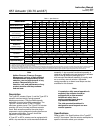
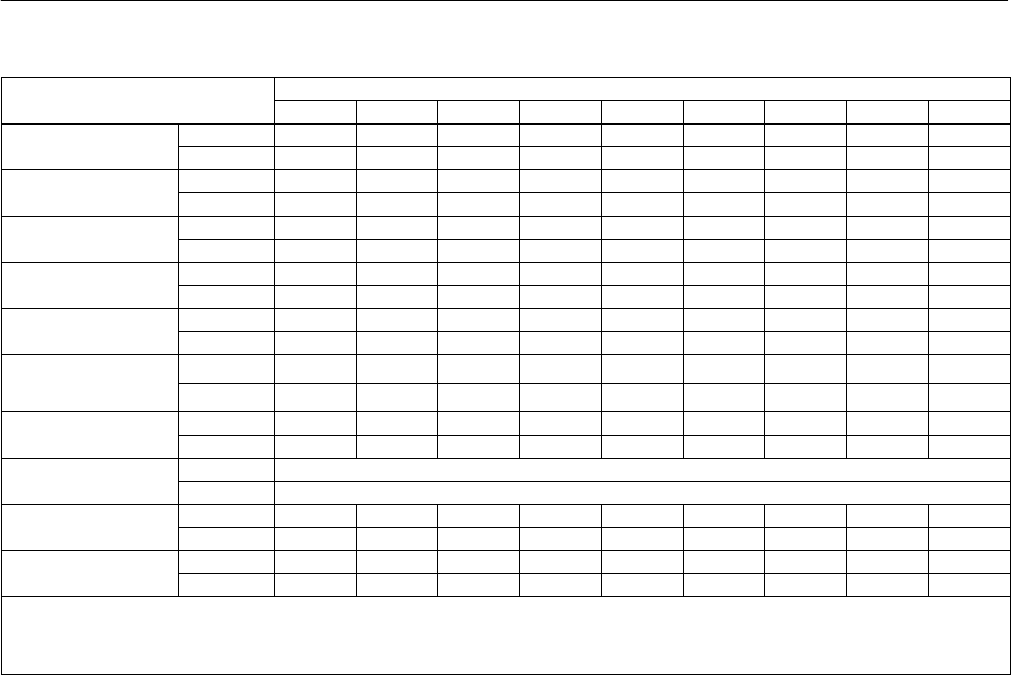
Table 1. Specifications
SPECIFICATION
(1)
ACTUATOR SIZE
SPECIFICATION
(1)
30 34 40 45 46 50 60 70
(1)
87
(1)
Nominal Effective Area
cm
2
297 445 445 677 1006 677 1006 1419 1419
Nominal Effective Area
Inch
2
46 69 69 105 156 105 156 220 220
Yoke Boss Diameters
mm 54 54 71 71 71 90 90 90 127
Yoke Boss Diameters
Inches 2-1/8 2-1/8 2-13/16 2-13/16 2-13/16 3-9/16 3-9/16 3-9/16 5
Acceptable Valve
mm 9.5 9.5 12.7 12.7 12.7 19.1 19.1 19.1 25.4
Acceptable
Valve
Stem Diameters
Inches 3/8 3/8 1/2 1/2 1/2 3/4 3/4 3/4 1
Maximum Allowable
N 10230 10230 12010 25131 33582 25131 30246 39142 39142
Maximum
Allowable
Output Thrust
(4)
Lb 2300 2300 2700 5650 7550 5650 6800 8800 8800
Maximum Travel
(2)
mm 19 29 38 51 51 51 51 76
(3)
76
(3)
Maximum Travel
(2)
Inches 0.75 1.125 1.5 2 2 2 2 3
(3)
3
(3)
Maximum Casing
Pressure for
Bar 8.6 4.5 4.5 3.4 2.8 3.4 2.8 3.8 3.8
Pressure for
Actuator Sizing
(4)
Psig 125 65 65 50 40 50 40 55 55
Maximum Diaphragm
Bar 9.6 5.2 5.2 4.1 3.4 4.1 3.4 4.5 4.5
Maximum
Diaphragm
Casing Pressure
(4)(5)
Psig 140 75 75 60 50 60 50 65 65
Material Temperature
_C Nitrile Elastomers: –40 to 82_C, Silicone Elastomers: –54 to 149_C, Fluorocarbons: –18 to 149_C
Material
Temperature
Capabilities
_F Nitrile Elastomers: –40 to 180_F, Silicone Elastomers: –65 to 300_F, Fluorocarbons: 0 to 300_F
Pressure Connections
1/4 In. NPT X X X X X X X - - - - - -
Pressure
Connections
(female)
1/2 In. NPT - - - - - - - - - - - - - - - - - - - - - X X
Approximate Weights
kg 16 22 23 37 49 42 53 107 116
Approximate Weights
Lb 36 48 51 82 107 92 116 235 255
1. These values also apply to the Type 657-4 actuator construction.
2. Actuator travel may be less than the value listed after connecting the actuator to the valve.
3. Maximum travel for Type 657-4 is 102 mm (4 inches).
4. Normal operating diaphragm pressure must not exceed maximum diaphragm casing pressure and must not produce a force on the actuator stem greater than the maximum allowable
output thrust or the maximum allowable valve stem load. Contact your Emerson Process Management sales office with questions concerning maximum allowable valve stem load.
5. This maximum casing pressure is not to be used for normal operating pressure. Its purpose is to allow for typical regulator supply settings and/or relief valve tolerances.
Note
Neither Emerson, Emerson Process
Management, nor any of their affiliated
entities assumes responsibility for the
selection, use and maintenance of any
product. Responsibility for the
selection, use, and maintenance of any
product remains with the purchaser
and end-user.
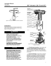
Description
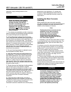
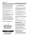
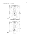
The Type 657 actuator (figure 1) and the Type 657-4
actuator are direct-acting, spring-opposed
diaphragm actuators. They provide automatic
operation of control valve body assemblies. The
Type 657 actuator offers 76 mm (3 inches)
maximum actuator travel. The Type 657-4 actuator
provides 102 mm (4 inches) maximum actuator
travel. Both actuators position the valve plug in
response to varying pneumatic loading pressure on
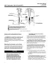
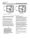
the actuator diaphragm. Figure 2 shows the
operation of these actuators.
A Type 657 or 657-4 actuator can be equipped with
either a top-mounted or a side-mounted handwheel
assembly. A top-mounted handwheel assembly is
used as an adjustable up travel stop to limit actuator
travel in the up direction (see figure 2). A
side-mounted handwheel assembly is usually used
as an auxiliary manual actuator. Adjustable
casing-mounted up or down travel stops are also
available for this actuator.
Note
If repeated or daily manual operation is
expected, the actuator should be
equipped with a side-mounted
handwheel rather than a
casing-mounted travel stop or
top-mounted handwheel.
The side-mounted handwheel is
designed for more frequent use as a
manual operator.
Specifications
Refer to table 1 for Specifications of the Type 657
and 657-4 actuators. See the actuator nameplate for
specific information about your actuator.