


657 Actuator (30-70 and 87)
Instruction Manual
Form 1900
February 2007
13
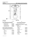
3. Remove the cap screws and casing screws and
nuts (keys 22 and 23), lift off the upper diaphragm
casing (key 1), and remove the diaphragm (key 2).
4. Remove the cap screw (key 3) and the washer
(key 25), then take off the diaphragm plate (key 4).
5. Remove the actuator spring (key 6), the upper
sleeve (key 34), and the spring seat (key 11) from
the yoke cylinder. This exposes the needle bearing
and races (keys 37 and 38).
6. Separate the halves of the stem connector
assembly (key 26) by removing the two cap screws.
Remove the actuator stem (key 10).
7. Remove the travel indicator (key 14).
CAUTION
To avoid possible product damage, do
not move the neutral indicator scale
after completing the following step.
8. Turn the handwheel to raise the lower sleeve
(key 46) until it is free of the worm gear (key 44). Lift
out the lower sleeve and the key (key 47). DO NOT
move the neutral indicator scale (key 59).
9. Loosen two set screws (key 40), then unscrew
the bearing retainer flange (key 39) and the attached
spring adjuster (key 12), using a suitable tool in the
open neck of the flange. Take out the gear and two
needle bearings (key 42), one on each side of the
gear.
10. Remove the spring adjuster (key 12) from the
bearing retainer flange (key 39). If desired, the worm
shaft (key 45) and associated parts can be
disassembled to replace or lubricate them. To do so,
first remove the stop nut (key 54) and the handwheel
(key 51). Do not lose the small ball (key 55) and
spring (key 56).
11. Loosen the two set screws (key 41), and
unscrew the front and back retainers (keys 48
and 49). The ball bearings (key 50) will come out
with the retainers. Remove the worm shaft (key 45).
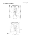
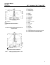
Assembly for Side-Mounted Handwheel
(Size 70 & 87)
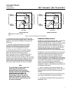
1. The front and back retainers (keys 48 and 49)
each have a slot in their threads for a set screw
(key 41). Pack the ball bearings (key 50) with
anti-seize lubricant (key 244), and insert one ball
bearing into the back retainer (key 49) as shown in
figure 13.
2. Thread the back retainer and ball bearing
(keys 49 and 50) into the yoke (key 9). Align the slot
in the bearing retainer with the set screw hole in the
yoke, insert the set screw (key 41), and tighten it.
3. Coat the worm shaft (key 45) threads with
anti-seize lubricant (key 244), and slide the shaft into
the yoke so that the end of the shaft fits snugly into
the back retainer (key 49).
4. Insert the bearing into the front retainer (key 48),
and thread the retainer and ball bearing into the
yoke (key 9). Align the slot in the retainer with the
hole in the yoke, insert the set screw (key 41), and
tighten it.
5. Put the spring and ball (keys 56 and 55) into the
handwheel (key 51). Slide the handwheel onto the
worm shaft (key 45). Thread the stop nut (key 54)
onto the shaft.
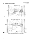
6. Pack the two needle bearings (key 42) and coat
the worm gear (key 44) threads with anti-seize
lubricant (key 244). Insert the key (key 47), the
bearings, and the gear into the yoke (key 9) as
shown in figure 13.
7. Slots are cut into the threads of the bearing
retainer flange (key 39). Thread the flange into the
yoke (key 9) so that the slots and the holes for the
set screws (key 40) align. Insert the screws, and
tighten them.
8. The lower sleeve (key 46) has milled slots in one
end. Coat the sleeve threads with lithium grease
(key 241), then slide the end of the lower sleeve with
the milled slots into the bearing retainer flange
(key 39).
9. Turn the handwheel (key 51), and feed the sleeve
through the gear so that the slot in the lower sleeve
(key 46) engages the key (key 47) in the yoke
(key 9). Continue turning the handwheel until the
lower sleeve protrudes 93.7 mm (3.69 inches) below
the surface of the yoke. The pin in the side of the
lower sleeve should line up with the extension on the
neutral indicator.
10. Slide the square end of the actuator stem
(key 10) through the lower sleeve (key 46) so the
stem contacts the valve stem. Clamp both stems in
the two halves of the stem connector (key 26). The
stem connector should not be closer than 3.2 mm
(1/8 inches) to the lower sleeve when the actuator
stem is in the retracted position. This adjustment will
provide approximately 3.2 mm (1/8 inches) of free
travel of the lower sleeve in either direction for
manual operation. Fasten the stem connector halves
together with the cap screws.