


6. Connect AC power to “L1” and “L2” (CB1) —120 Volt, 60 Hz or as called for on controller data
plate.
7. Connect remote normally open START push-button wires to terminals “13” and “14” (if used).
8. If deluge valve is used, remove jumper from terminals “16” and “17”. Connect wires from normally
closed contact on deluge valve to terminals “16” and “17”.
9. Connect remote normally open shutdown interlock wires to terminals “15” and “16” (if used). A
factory installed jumper will be installed on these terminals. If installing a interlock, this jumper
may be removed, otherwise leave jumper in place until the set up of the Mark II
XG is complete.
10. Check to see that all connections are both correctly wired (in accordance with fi eld connection
diagram) and tight.
11. Close enclosure door.
MAKING SYSTEM PRESSURE CONNECTIONS
The FTA1100 controller requires one (1) “System Pressure” connection from the system piping
to the enclosure. The connection fi tting, 1/2” FNPT, is provided on the bottom, external side of the
enclosure for this purpose.
The “Test Drain” connection, located to the left of the “System Pressure” connection, should
be piped to a vented drain or to waste. The “Test Drain” is used only briefl y during the weekly test
cycle.
Note—Test drain line must be free fl owing. Do not use any valves or plugs on this line.
Refer to NFPA 20 for correct fi eld piping procedure of sensing line between the pumping system
and the controller.
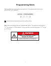
PROGRAMMING THE MARK IIXG
1. Energize (Turn “ON”) circuit breakers 1CB (AC Power), 2CB & 3CB (Battery Connections). Follow
the programming instructions included in this manual to set pressure, timers, etc...
2. When all programming is complete and the unit is ready to put into service, remove interlock
jumper wire from terminals 15 & 16. This jumper is factory installed to prevent starting of the
engine during installation and setup.
4