


2. Verify that the controller information is what is required on the project:
• Firetrol catalog number
• Engine voltage and polarity of grounding
• Incoming line voltage and frequency
• Maximum system pressure
3. Project electrical contractor must supply all necessary wiring for fi eld connections in accordance
with the National Electrical Code, local electrical code and any other authority having jurisdic-
tion.
4. Refer to the appropriate fi eld connection drawing for wiring information.
Procedure—
All engine connections, remote alarm functions and AC wiring must be brought into the enclo-
sure at the bottom. (See dimension drawing for exact location). A gland plate is supplied for ease of
installation.
Proceed as follows:
1. Use a hole (conduit) punch, not a torch nor a drill, and punch a hole in the gland plate for the size
conduit being used.
2. Install necessary conduit.
Warning—Use only gland plate for conduit entrance. Controller warranty is VOID if any other
location is used.
Note—All fi eld wiring connections are connected to terminal blocks located in the controller.
Terminals for interconnection to the corresponding numbered terminals on the engine terminal
block are located between the circuit breakers (CB1, AC power and CB2-CB3, battery connections).
Not all engines require all terminals to be connected. Reference engine wiring diagram and Field
Connection Diagram for appropriate information. Other terminals are for connecting remote
alarm functions and optional features are located on the controller relay board(s).
AC line connections are made to terminals L1 and L2 (1CB). A ground lug, marked “G” is provided
for grounding. This AC circuit should come from a source having a circuit breaker sized in accor-
dance with the National Electrical Code and other local codes.
3. Pull all wires necessary for engine connections, remote alarm functions, AC power and all other
optional features. Allow enough excess wire inside enclosure to make up connections to the ter-
minal block. Be sure to consult the appropriate fi eld connection diagram. Make sure AC Circuit
Breaker (CB1) and Battery Circuit Breakers (CB2, CB3) are turned “Off”.
Warning—Do not use controller wire way for routing external wiring.
Wire Sizes—
• Use #14 AWG wire minimum for all electrical connections except for battery charger connec-
tions. (Battery chargers connected to terminals 6, 8, and 11.)
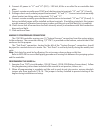
• On terminals 6, 8, and 11, use the following information to determine wire sizes:
4. Make all fi eld connections to remote alarm functions and any other optional features.
5. Verify AC line voltage and frequency with the controller data plate on the enclosure door prior to
energizing AC power.
0’ to 25’ (0 to 7.62 m.)
25’ to 50’ (7.62 m. to 15.24 m.)
Linear feet (in conduit run)
from controller to terminal
block on engine
Maximum
Wire Size
#10 AWG (6 mm
2
)
#8 AWG (10 mm
2
)
3