


These instructions are intended to assist in the understanding of the installation and operation of
the FTA1100. Read through these instructions thoroughly prior to connecting the controller. If there
are any questions unanswered in these instructions, please contact the local Firetrol representative
or factory service department.
INTRODUCTION
Firetrol
®
FTA1100 combined automatic and manual diesel engine fi re pump controllers are intended
for starting and monitoring fi re pump diesel engines. They are available for use with 12 or 24 volt
negative ground systems using lead acid or Nickel-Cadmium batteries. FTA1100 fi re pump controllers
are listed by Underwriters Laboratories Inc., in accordance with UL218, Standard for Fire Pump Control-
lers, CSA, Standard for Industrial Control Equipment (cUL), and approved by Factory Mutual. They are
built to meet or exceed the requirements of the approving authorities as well as NEMA and the latest
editions of NFPA 20, Installation of Centrifugal Fire Pumps, and NFPA 70, National Electrical Code.
MOUNTING CONTROLLER—
Note—Consult the appropriate job plans to determine controller mounting location. Controller must
be mounted within view of the engine.
Tools and Materials (all mounting):
1. Assortment of common hand tools of the type used to service electromechanical equipment.
2. Hole (conduit) punch.
3. Drill for drilling wall/fl oor anchor holes.
4. Hand level.
5. Tape measure.
6. Four (4) anchors with bolts and washer—if wall mount. Six (6) anchors, bolts and washers—if fl oor/
base mount.
Wall Mount—
Procedure—
1. Locate bottom mounting brackets and hardware.
2. Inspect for damage.
3. Gently lay the controller on its back, using protection so the paint is not damaged. It is best to lay
the controller in a location that is out of the way from actual mounting location.
4. Attach each bracket to the bottom of the enclosure using the supplied hardware . Tighten nuts
securely.
Note—Refer to the controller dimension drawing for necessary mounting dimensions.
The controller is wall mounted by using four (4) wall anchors, 2 anchors for the top ears and 2
anchors for the bottom mounting brackets. The ears and brackets are dimensionally on the same
center-line for ease in mounting.
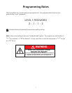
1
WARNING
RISK OF ELECTRICAL SHOCK
Personal injury could occur.
Ensure all power is disconnected before
installing or servicing this equipment.
WARNING
RISK OF PERSONAL INJURY
Controller cannot stand upright with the bottom
mounting brackets attached. Leave laying on its
back until the wall anchors are ready for controller
installation.