


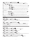
5. Using either the dimension print or by measuring the distance between the center lines of the 2
lower bracket slots, transcribe this dimension onto the wall. Note: The bottom edge of the en-
closure should be a minimum of 12” (305 mm.) from the fl oor in case fl ooding of the pump room
occurs.
6. Drill and put 2 anchors into the wall for the 2 lower bracket slot mounts.
7. Mark on the wall, the location of the holes in the upper mounting ears.
8. Drill and put 2 anchors into wall for the upper mounts.
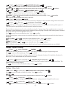
9. Install bolts and washers in 2 lower anchors, leaving a gap between the washer and wall.
10. Lift the controller and place the bottom mounting slots down onto the 2 lower anchor bolts. Do
not tighten bolts.
11. Align holes in upper mounting ears and install 2 bolts and washers in anchors.
12. Shim anchors as necessary to ensure rear of enclosure is vertically level and enclosure is not
stressed. Tighten all 4 anchor bolts.
13. Check to be sure enclosure door opens and closes freely and that enclosure is level.
Floor/Base Plate Mount—
Procedure–
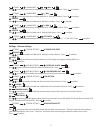
MOUNTING LEGS (OPTIONAL - IF ORDERED)
Procedure—
1. Unpack legs and mounting hardware.
2. Inspect legs for damage.
3. Gently lay the controller on its back, using protection so the paint is not damaged. It is best to lay
the controller in a location that is out of the way from actual mounting location.
4. Attach each leg to the bottom of the enclosure using the provided hardware . Tighten nuts se-
curely.
5. After legs are securely attached, stand the controller up on its legs for mounting. Each leg has 3
holes on the bottom for anchoring to the fl oor or base plate.
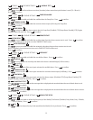
Note—Consult the appropriate job plans to determine controller mounting location.
Refer to the controller dimension print for necessary mounting dimensions.
The controller is fl oor/base plate mounted by using the 3 pre-drilled holes in each leg. The holes
are dimensionally on the same center line for ease in mounting.
6. Using either the dimension print or by measuring distance between the center lines of the holes
on one leg, transcribe these dimensions onto the fl oor/base plate.
7. Drill 3 holes in fl oor/base plate for anchoring the leg.
8. Mark location of holes for opposite leg and drill 3 more holes.
9. Secure controller to fl oor/base plate with bolts and washers and tighten.
10. Check to be sure enclosure door opens freely and that enclosure is level.
MAKING ELECTRICAL CONNECTIONS
Important Precautions—
Prior to making any fi eld connections:
1. Open door of enclosure and inspect internal components and wiring for any signs of frayed or
loose wires or other visible damage.
2
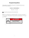
WARNING
RISK OF PERSONAL INJURY
Controller is not free standing! Controller must be
secured to floor or wall surface before opening
door or operating.