


©
2003
Directed Electronics, Inc.
7
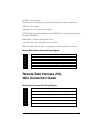
Primary Harness (H1) Wire Connection Guide
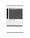
Primary Harness (H1) Wiring Diagram
___
___
___
___
___
___
___
___
___
___
___
___
Primary Harness Wire Descriptions
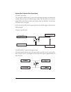
H1/1 ORANGE (-) Ground-When-Armed Output
This wire supplies a (-) 500 mA ground as long as the system is armed. This output ceases as soon
as the system is disarmed. The orange wire is pre-wired to control the 8618 starter kill relay.
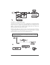
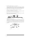
NOTE: If using the H1/1 ORANGE wire to activate an add-on accessory such as window
automation, pager or voice module a 1 Amp diode must be installed to ensure proper operation.
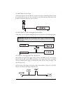
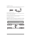
Insert the diode as shown in the following diagram.
IMPORTANT! Never interrupt any wire other than the starter wire.
RED/WHITE (-) 200 mA Channel 2 Output
RED (+) Constant Power Input
BROWN (+) Siren Output
OPEN No Wire
BLACK (-) Chassis Ground Input
VIOLET (+) Door Trigger Input, Zone 3
BLUE Multiplexed Trigger Input, Zone 1
GREEN (-) Door Trigger Input, Zone 3
BLACK/WHITE (-) 200 mA Domelight Supervision Output
WHITE/BLUE (-) Remote Start Activation Input
WHITE (+)/(-) Selectable Light Flash Output
ORANGE (-) 500 mA Armed Output
H1/1
H1/2
H1/3
H1/4
H1/5
H1/6
H1/7
H1/8
H1/9
H1/10
H1/11
H1/12