


©
2003
Directed Electronics, Inc.
15
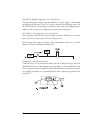
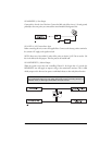
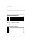
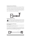
ORANGE (+) Accessory Output
Connect this wire to the accessory wire in the vehicle that powers the climate control system.
PURPLE (+) Starter Output
Connect this wire to the starter wire in the vehicle.
NOTE: If failsafe starter kill is installed, be sure the PURPLE wire is connected to the car side of
the failsafe starter kill relay.
PINK/WHITE (+) Output to Second Ignition Circuit
Connect this wire to the second ignition wire in the vehicle.
NOTE: For vehicles that do not have a second ignition wire, this connection is not required.
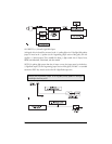
Remote Start Ribbon Harness Wiring Diagram
___
___
___
___
___
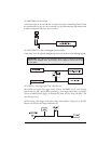
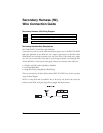
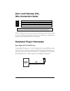
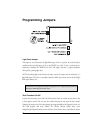
Remote Start Harness (H3),
Wire Connection Guide
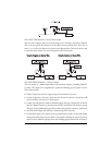
Remote Start Harness (H3) Wiring Diagram
___
___
___
___
___
___
BLACK/WHITE (-) Neutral Safety Switch Input
VIOLET/WHITE Tachometer Input Wire
BROWN (+) Brake Switch Shutdown Wire
GRAY (-) Hood Pinswitch Shutdown Wire
BLUE/BLACK (-) 200 mA Optional Third Ignition Output
BLUE (-) Status/Factory Security Rearm Output
1
2
3
4
5
6
RED (+) Constant Power
YELLOW (+) Ignition Input to Remote Start
PINK (-) 200 mA Ignition Relay Turn-On
ORANGE (-) 200 mA Accessory Relay Turn-On
PURPLE (-) 200 mA Starter Relay Turn-On
1
2
3
4
5