


14
©
2002
Directed Electronics, Inc.
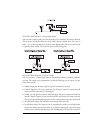
Relay Satellite Ignition Switch Interface
Wire Connection Guide
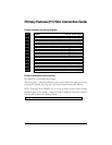
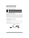
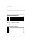
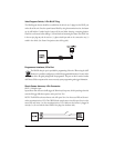
Heavy Gauge Relay Satellite Wiring Diagram
All except the red heavy gauge wires leading from the relay satellite are used to energize high current
circuits in the vehicle. It is crucial that these connections are made correctly so that they are capable
of handling the current demands. For this reason, scotch locks, T-taps and other such connectors
should not be used.
___
___
___
___
___
___
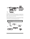
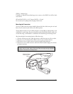
Heavy Gauge Relay Satellite Wire Descriptions
RED (2) (+)12V Input for Relays
Remove the two 30 amp fuses prior to connecting these wires and do not replace them until the
satellite has been plugged into the control module. These wires are the source of current for all the
circuits the relay satellite will energize. They must be connected to a high current source. Since the
factory supplies (+) 12V to the key switch that is used to operate the motor, it is recommended that
these wires be connected there.
NOTE: If the factory supplies two separate (+) 12V feeds to the ignition switch, connect one RED
wire of the satellite to each feed at the switch.
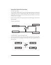
PINK (+) Ignition Output
Connect this wire to the ignition wire in the vehicle.
PINK/WHITE (+) Output to Second Ignition Circuit
PURPLE (+) Output to Starter Circuit
ORANGE (+) Output to Accessory Circuit
PINK (+) Output to Ignition Circuit
RED (+) High Current 12V Input
RED (+) High Current 12V Input
1
2
3
4
5
6
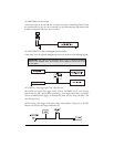
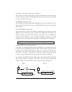
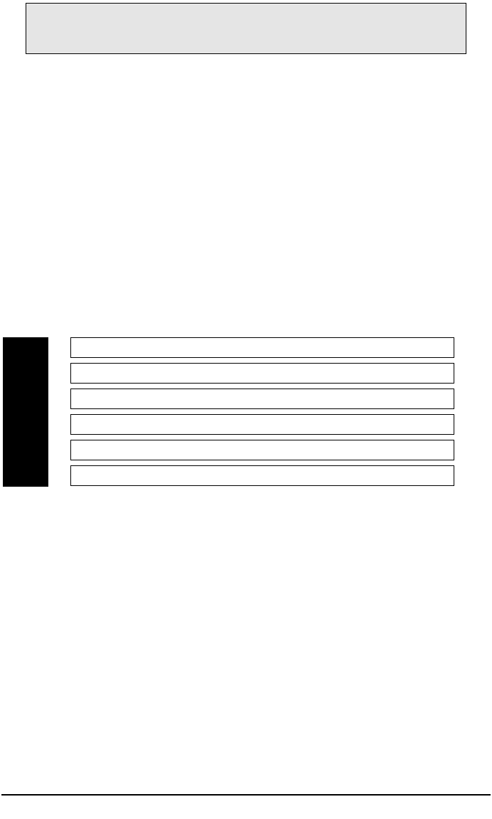
IMPORTANT! Never use this wire to drive anything but a relay or a low-current input!
This transistorized output can only supply 200 mA, and connecting directly to a
solenoid, motor, or other high-current device will cause the module to fail.