bühler
2500 Bale Carrier
51
APPENDIX C
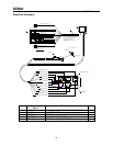
Electrical Assembly
WARNING
Read and understand the safety messages listed in the 2500
Bale Carrier operator manual. Shut off all power to unit before inspecting, servicing,
adjusting or repairing the 2500 Bale Carrier.
WARNING
For proper operation of the Snubber, power must be supplied
to the RED power wire from the control handle. Ensure that there is a 15 amp fuse in
place to protect this circuit. Verify prior to installing Snubber. Incorrect wiring will result
in electrical failure.
NOTE:
The snubber unit is designed to protect the momentary control switches.
The snubber minimizes coil voltage discharge during the de-energizing of the valve
solenoid coils. There are no serviceable parts within the unit. Ensure that all electrical
connections are clean and dry. Test the 2500 Bale Carrier and view to see if the
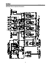
hydraulic system is operating correctly. If any wires are damaged or cut, the schematic
on the next page will assist in repair and maintenance. All wire is 18 gage.
Table of Contents
Description Page
Electrical Schematic………………………………………………………………...
52
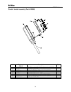
Electrical Assembly …………………………………………………………………
53


