


bühler
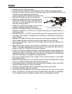
2500 Bale Carrier
24
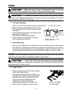
Align the lift cylinder rod and reinstall the pin.
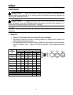
Adjust the outside bale fork to be positioned at the end of the lift arm and the
inner bale fork about 36” (91 cm) from the end.
Recheck all hardware so that every bolted connection on the lift arm is torqued
according to the specifications of the bolt chart.
Approach the bale and inspect to ensure the spacing of the forks is accurate.
For first operation, cycle the lift arm slowly with a bale and inspect just before
lifting bale from ground.
Finish the cycle and observe how the bale transits from the forks to the carrier
beam. If transition is smooth with minimum bale binding, assembly is completed.
If not, adjust the forks to a different location and try until loading is smooth.
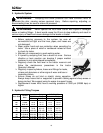
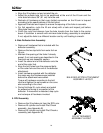
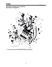
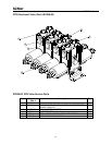
4. Bale Deflector Arm Assembly
Remove all hardware that is included with the
deflector assembly.
Remove the two top bolts from outer fork on
lift arm.
Maintain the spacing of the forks if already
preset. If not, set spacing as described in the
fixed pick up arm assembly section.
Insert the coned end of the deflector onto the
end of the outer fork.
Align the bolt holes from the removed bolts
on the outer fork and the end of the deflector
attachment.
Insert hardware supplied with the deflector
the same way the hardware was installed
before the attachment was added.
Torque all hardware according to the bolt
chart and tighten the set screws on the cone
also according to the chart.
During first bale lift, cycle slowly and watch
for excessive flexing or movement of the
deflector. If movement is detected, stop cycle
and re-torque all hardware involved.
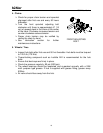
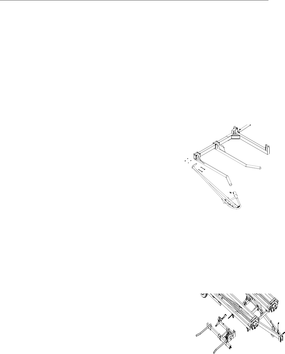
5. RPU Assembly
Remove the lift cylinder pin from the RPU arm.
Remove lift cylinder and install Pilot Check
assembly (see Appendix B)
Remove lift cylinder and install Pilot Check a
assembly (see Appendix B)
BALE DEFLECTOR ATTACHMENT
ASSEMBLY LAYOUT
RPU ATTACHMENT
ASSEMBLY LAYOUT