


bühler
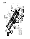
2500 Bale Carrier
10
OPERATION
CAUTION
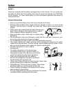
Prior to operation ensure the operator has read and
understands the safety requirements of the 2500 Bale Carrier. Ensure the pre-operation
checks have been completed prior to operation.
1. Attaching Bale Carrier To Tractor
CAUTION
Shut off tractor, engage parking brake and remove key before
working around 2500 Bale Carrier. Refer to tractor manual for tractor parking
procedures.
CAUTION
Use only the drawbar to couple the 2500 Bale Carrier to the
tractor. Ensure drawbar is capable of handling the 2500 Bale Carrier load. The tractor
must have a minimum mass of 25000 LB (11340 kg) and recommended 100 hp (75 kw).
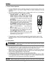
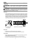
Using the tongue jack, raise tongue to align with hitch pin, adjust clevis position
as necessary to level the carrier beams.
Position tractor and secure with locking type drawbar pin (not supplied). Use an
approved hitch pin with a mechanical retainer.
Route safety chain around the hitch clevis, around drawbar support and back
hook. Refer to tractor manual for further drawbar instructions.
Do not use intermediate support on drawbar as attaching point.
Store safety chain off the ground when not in use. If safety chain is damaged in
any way, contact your dealer for a replacement.
For serial number 08BM2500001 and later, open-center valve is a factory-
installed feature
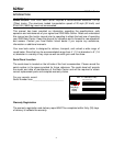
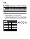
Note: The bale carrier is factory-configured to operate with tractors
having CLOSED-CENTER hydraulic systems (page 27).
For tractors with OPEN-CENTER or LOAD-SENSING hydraulic systems,
refer to the configuration on pages (29, 46 and 47).
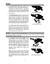
2. Attaching Bale Carrier Controls To Tractor
Bale raise and push functions are controlled by the 2500 Bale Carrier valve.
Pressure and tank are supplied by two hoses complete with black hydraulic tip
covers. The retract hose is designated with a check valve and ensures proper
flow through the valve. Connect tank hose to retract circuit and extend hose to
opposite extend port see Appendix B for schematic.
The tilt function is controlled by the tractor’s remote valve. Extension and
retraction are supplied by two hoses complete with red hydraulic tip covers.
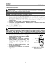
Connect control handle harness to the machine harness. Connection is made at
the snubber unit by matching the appropriate socket and plug.