


bühler
2500 Bale Carrier
25
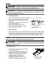
Reinstall cylinder at base end only.
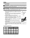
Lubricate all pins involved in RPU attachment with a SAE multi purpose grease
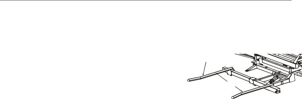
Align arm to pivots with open end of arm facing away from the 2500 Bale Carrier and
reinstall pins with hardware provided and
torque to specifications called for in the bolt chart.
Align the lift cylinder rod and reinstall the pin.
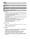
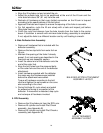
Adjust the outside bale fork to be positioned at
the end of the lift arm and the inner bale fork 6”
(15 cm) to 8” (20 cm) bigger than the size of
bale that is being loaded.
Install the hydraulics according to the way the
hydraulic assembly Appendix B calls for.
Recheck all hardware so that every bolted and
hydraulic connection on the lift arm is torqued according to the specifications of
the torque charts.
Depress lift arm up. The RPU cycle should begin with a squeeze action, then lift
and rotate. After rotation is complete the lift continues until the bale is above the
carrier beams.
Release LIFT ARM UP when bale is above the carrier beam. Depress LIFT ARM
DN to release the bale and return to ground level ready for the next bale.
For the first operation, cycle the lift arm slowly with the bale and observe the
RPU operation.
Approach the bale slowly; once the bale is captured in the forks press the lift
switch. The bale is squeezed until the pressure in the sequence valve which is
preset at 1800 PSI (12400 KPA) has been achieved.
If bale is not held in between the forks increase the sequence valve pressure by
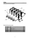
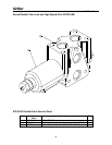
turning the setscrew clockwise. Refer to the RPU Rotate Cylinder drawing for
adjustment location of the setscrew. Verify that the fork spacing is accurate and
refer to the drawing on this page for fork adjustments.
The lift and rotate sequence won’t begin until the clamp pressure is met within
the sequence valve.
When the clamp pressure is met, the lifting action should start before the rotating
action to minimize bale damage from the moving ground.
To increase lift prior to rotate turn the restrictor knob clockwise. Refer to the RPU
Rotate Cylinder drawing for more information.
Continue to raise the bale until it is positioned above the carrier beam.
To release the bale, press lift arm down.
Finish the cycle and observe how the bale transits from the forks to the carrier
beam. If transition is smooth with minimum bale binding, assembly is completed.
If not, adjust the forks to a different location and try until loading is smooth.
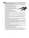
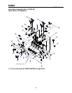
ROTATING PICK UP ARM
ADJUSTABLE FORK
BALE WIDTH + 6” TO 8”