


bühler
2500 Bale Carrier
23
CAUTION
Make sure area is clear of obstructions, well lit, and has
sufficient room for safe assembly. Do not work underneath raised assembly.
CAUTION
Ensure the carrier’s tires and hitch are securely blocked.
Otherwise, verify the 2500 Bale Carrier is properly coupled to the drawbar on a tractor
with a minimum of 25000 LB (11340 kg).
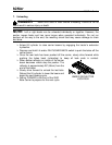
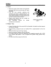
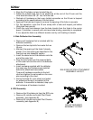
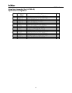
1. Tail Light Assembly
Refer to carrier final assembly drawing in Appendix D.
Remove all required hardware from parts box.
Ensure taillights are installed correctly, refer to
illustration.
Connect the tail light wiring harnesses to their
appropriate connections.
Connect main lighting plug to tractor.
Test by verifying correct lamps illuminate
when signalling and braking.
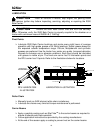
2. Centre Bale Stop
Remove the hardware that is attached to the center bale stop and place center
bale stop bar on bolt plates in the position shown at the beginning of the manual.
Torque the provided hardware to the specifications listed on the bolt chart. Tie
wrap the hydraulic hoses that run to the lift and tilt cylinders under the roll bar.
NOTE:
Hydraulic Assembly methods and layouts are common to the right and left
sides. Only one side of each component is shown in this manual.
CAUTION
Stay clear of the arms when testing a finished assembly.
Ensure during assembly to keep your entire body out from underneath parts that are
being attached to the main frame.
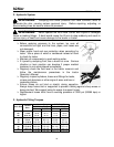
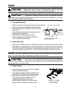
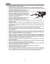
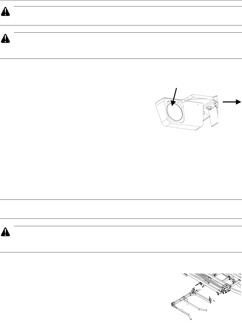
3. Fixed Lift Arm
Remove lift arm pivot pins that are installed
on the 2500 Bale Carrier.
Thoroughly lubricate all pins involved in the
assembly with a SAE multi purpose grease.
Align arm to pivots with open end of arm
facing forward and reinstall pins with
hardware provided and torque to
specifications called for in the bolt chart.
Remove the lift cylinder pin from the arm.
36.0"
FIXED LIFT ARM
ATTACHMENT
VIEWED FROM THE FRONT
RIGHT HAND SIDE
TO
CENTER
OF
HAYLINER
YELLOW LENS OUTSIDE