


128-8605
7 of 20
7
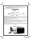
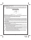
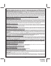
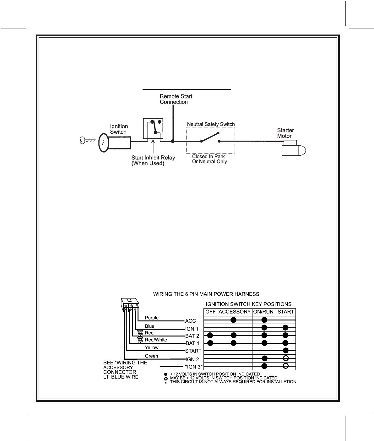
Note: This wire must be connected to the vehicle side of the starter cut relay (when used). For the electrical
neutral switch configuration, this connection must be made between the starter inhibit relay, (when
used) and the neutral safety switch as shown in the following diagram.
Failure to connect this wire to the ignition switch side of the neutral safety switch can result in
personal injury and property damage.
SEE NEUTRAL START SAFETY TEST FOR FURTHER DETAILS.
YELLOW START WIRE DETAIL
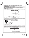
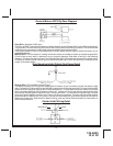
BLUE Wire: Ignition 1 Output
Connect this wire to the ignition 1 wire from the ignition switch. This wire will show +12 volts when the ignition
key is turned to the "ON" or "RUN" and the "START" or CRANK" positions, and will have 0 volts when the key
is turned to the "OFF" and "ACCESSORY" positions.
For Diesel Applications, this wire must be connected to the ignition circuit that powers the glow plugs if the
vehicle requires glow plug pre-heating. (See selectable feature #9)
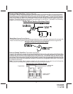
GREEN Wire: Ignition 2 Output
Connect this wire to the ignition 2 wire from the ignition switch. This wire will show + 12 volts when the ignition
key is turned to the "ON" or "RUN" position and is some cases the "START" or CRANK" position. This wire
will show 0 volts when the key is turned to the "OFF" and "ACCESSORY" positions.
Note: See programming information concerning this wire to allow output during the "START" mode.
VIOLET Wire: Accessory Output
Connect this wire to the Accessory wire from the ignition switch. This wire will show + 12 volts when the
ignition switch is turned to the "ACCESSORY" or "ON" and "RUN" positions, and will show 0 volts when the
key is turned to the "OFF" and "START" or "CRANK" positions.