


128-8605
13 of 20
13
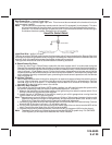
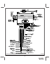
Note!When installing this system as a stand alone passive security system, the RED wire in this
connector must be connected to a rest at ground , + 12 VDC switched ignition source. RED w/BLACK,
GREEN & GREEN/BLACK wires must be connected to ground. The BLUE wire in this connector will not
be required for the stand alone installation. The Trigger Input, feature # 18 must be set for delay instead
of instant, to insure the consumer has time to get into the vehicle and turn the ignition on before the alarm triggers.
The Green/Black, Red, Green, and Red/Black wires of the 5 pin connector are polarity learning inputs to be
connected to the vehicle lock & unlock 1, and lock & unlock 2 control wires. When the control circuit is first
powered up, these wires will learn the resting state of the circuits they are connected to. DO NOT operate the
vehicle's door lock circuits, (switch or remote), while power is being applied to this upgrade alarm system.
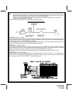
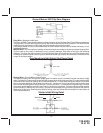
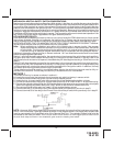
WIRING THE ARM / DISARM INPUTS IN VEHICLES WITH REMOTE 2 STEP UNLOCK
The following represents the most common wiring routine in vehicles using the remote 2 step unlock feature.
GREEN/BLACK WIRE : ARM INPUT #2
Connect this wire to the vehicles door lock switch input wire, which will receive either a switched positive or
switched negative when the door lock switch is moved to the lock position. This wire will be used to compare
the two inputs Arm #1 & Arm #2. If both inputs are active at the same time, the vehicle will not arm. The intent
of this wire is to prevent the system from arming when the in vehicle door lock switch is used to lock the doors,
insuring only the transmitter arms the system. If you do not desire this feature or the customer prefers that the
door lock switch arm the system as well as the transmitter, connect this wire to chassis ground.
RED WIRE : DISARM INPUT #1
Connect this wire to the driver's door unlock motor wire, which will receive a negative or positive pulse when the
drivers door is unlocked with the remote transmitter, and the door switch, but does not receive a pulse when
all doors are unlocked using the remote transmitter.
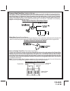
GREEN WIRE : ARM INPUT #1
Connect this wire to the lock side of the door lock/unlock switch or, the driver's door lock motor leg wire, which
will receive a negative or positive pulse when the doors are locked using the door switch or the remote transmitter.
RED w/BLACK TRACE WIRE : DISARM INPUT #2
Connect this wire to the unlock side of the door lock/unlock switch or any passenger door unlock motor wire,
which will receive a negative or positive pulse when all doors are unlocked using the door panel switch or the
remote transmitter, but will not receive a pulse when the driver only door is unlocked using the remote
transmitter.
NOTE: The Green/Black, Red, Green, & Red/Black wires MUST be connected to their respective source before
powering up the module as these wire are polarity learn and will not function properly if connected after power
up. In addition, these wires if not used as indicated above must be connected to ground. This will insure
proper operation and prevent inadvertent arming and disarming unintentionally.
BLUE WIRE : TRUNK TRIGGER SHUNT INPUT
This wire will determine if the vehicle’s trunk has been opened using the OEM transmitter, and prevent the alarm
from triggering when the factory transmitter is used. This wire requires a positive trigger input and must be wired
to the switched + 12 volt trunk control wire from the vehicle's keyless entry unit or, the switched + 12 volt side
of the vehicle's trunk release solenoid.
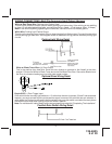
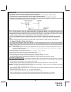
WIRING THE ARM / DISARM INPUTS IN VEHICLES WHEN THE SYSTEM IS SET UP AS A STAND ALONE
PASSIVE (IGNITION CONTROL) ALARM SYSTEM
For this mode of operation, be certain to set selectable features # 6 for passive arm, feature #18 for trigger delay.
GREEN/BLACK & GREEN WIRE: ARM INPUTS
Connect these wires to chassis ground.
RED WIRE : DISARM INPUT #1
Connect this wire to an ignition source that has +12 volts when the ignition switch is turned to the on and start
positions and has 0 volts when the switch is in any other position.
RED w/BLACK TRACE WIRE: DISARM INPUT #2
Connect this wire to chassis ground.
BLUE: TRUNK SHUNT INPUT
This wire is not used for the stand alone passive alarm application.
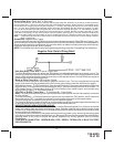
WIRING THE 4 PIN AUXILIARY OUTPUT HARNESS
The auxiliary 4 pin connector provides low current outputs to control various functions in the vehicle during
different stages of the Remote Start unit's operation. Understanding these outputs and the time in which they
occur will allow you to determine if they are needed for the particular vehicle you are working on as well as how
to use them.
Black w Blue Trace Wire: Pulsed Ground Output Before Start
The Black w/ Blue Trace wire will provide a 1 second 300 mA pulsed ground output 1.5 second before the
remote start unit activates as well as when the transmitter is used to disarm the system. Typical use for this