


128-8605
18 of 20
18
MECHANICAL NEUTRAL SAFETY SWITCH CONSIDERATIONS:
Mechanical neutral safety switch configurations differ slightly in that they do not offer the same level of safety
when installing a remote start device. Often when the ignition switch is turned off while the gear selector is in
any position other than park or neutral, the mechanical function will not allow the key to be turned to the start
position or be removed from the ignition cylinder. This configuration prevents mechanical operation while the
vehicle is in gear but offers no consideration for electrical operation. Because of this potential problem, this
installation requires the additional connection of a safety wire from the remote start device to the vehicle
Park/Neutral ECM Input or the vehicle key in sensor. This connection will prevent remote start operation if the
key is left in the ignition switch regardless of the gear selectors position.
KEY IN SENSOR CIRCUITS:
If the vehicle you are working on does not have or you cannot locate the ECM reference wire, there are two
alternatives available. Although not preferred, the vehicle Key In Sensor may be reconfigured to allow a
margin of safety and will prevent the vehicle with a Mechanical Neutral Start Switch from starting in gear.
AUDIOVOX ADVISES THAT YOU MAINTAIN THE FACTORY CIRCUIT WHENEVER POSSIBLE. The follow-
ing two circuits may be used only if the above circuit is not available.
Note: When completing an installation using either of the following key in sensor circuits, if the operator
inserts the ignition key while the vehicle is running under the control of the Remote Start, the vehicle
will shut down. This must be explained to the operator as it is in contrast to the normal operation of
a vehicle utilizing an electrical neutral start switch and is inconsistent with the operators manual.
Additional information concerning Key In Sensor methods 1 & 2 are listed below and should be reviewed
before considering either alternative.
Method 1 will allow the safety required for the remote start unit and prevent the vehicle from starting while in
any gear other than Park or Neutral while the key is in the ignition cylinder however, if the key is left in the
ignition switch and the door is left opened, the added relay will be energized causing a 150mA drain on the
battery.
Method 2 will allow the safety required for the remote start unit and prevent the vehicle from starting while in
any gear other than Park or Neutral while the key is in the ignition cylinder however, the original factory key
in chime module will not alert the owner that the key has been left in the ignition switch. In addition, this may
also effect other warning tones such as the light on reminder.
These situations should be carefully considered before altering the vehicle's wiring and must be fully ex-
plained to the consumer. Circuits may be used only if the above circuit is not available.
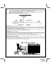
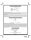
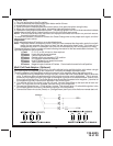
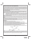
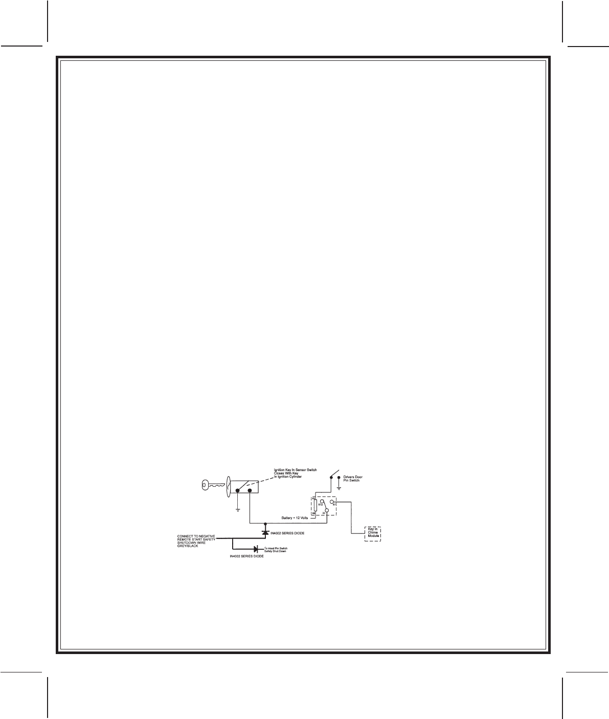
METHOD 1
To connect to the key in sensor as shown in method 1:
A. Locate the control wire that connects the drivers door pin switch to the key in sensor switch.
B. Cut this wire and connect the ignition cylinder side to chassis ground.
C. Locate the key in sensor switch wire that connects the chime module to the ignition cylinder.
D. Cut this wire and connect the ignition cylinder side to terminal 30 of a P&B VF45F11 or equivalent relay.
E. Connect the cathode (striped) side of a 4002 series diode to this same wire, and connect the (non striped)
side to the negative shut down safety wire (Gray / Black) of the Audiovox Remote Start Unit.
F. Connect terminal 86 of the relay to a fused +12 volt constant battery source.
G. Connect terminal 87 of the relay to the Chime Module side of the previously cut wire in step D.
H. Connect terminal 85 of the relay to the Drivers Door side of the pin switch wire previously cut in step B.
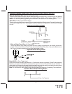
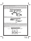
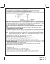
NOTE: A second 4002 series diode may be required to maintain the integrity of the hood open, shut down
circuit. If this is the case, it must be installed as shown in the diagram above. The anode (Non Striped) side
must be connected to the Gray/Black wire of the Remote Start Unit. The cathode (Striped) side must be
connected to the hood pin switch. If the hood pin switch is also used for an alarm trigger input, be certain to use
the dual diode setup as shown in this installation guide under the heading hood switch.