


128-8605
6 of 20
6
from all areas of the vehicle. The selected location must be within 18" of the control module to allow routing
and connecting of the 4 pin harness. Secure the shock sensor to the chosen location using two #8 self taping
sheet metal screws. The sensor can also be secured to an existing dash brace using cable tie straps.
Whichever mounting method is used be sure to allow access to the sensitivity adjustment potentiometer for
use later in the installation.
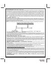
STARTER INHIBIT RELAY:
Select a mounting location within 12" of the ignition switch's low current start solenoid wire. Secure the relay
to an existing harness in the chosen location using a cable tie around the relay's wiring harness. Caution! Do
not wire tie the metal bracket to an existing wiring harness as vibration may cause chaffing and shorting
damaging the factory wiring. If an existing harness is not available then secure the relay's metal mounting tab
to an under dash metal brace with a #8 self taping sheet metal screw. Wire the relay as per the diagram found
later in this manual.
This system is to be used in vehicles with AUTOMATIC TRANSMISSIONS only! Although this combination
Alarm/Remote Start unit is a sophisticated system with many advanced features, IT MUST NOT be installed
into a vehicle with a manually operated transmission. Doing so may result in serious personal injury and
property damage.
IMPORTANT!
DO NOT PLUG THE SIX PIN MAIN POWER HARNESS OR THE MULTI PIN INPUT / OUTPUT HARNESS
INTO THE CONTROL MODULE UNTIL ALL CONNECTIONS TO THE VEHICLE HAVE BEEN MADE. AFTER
SELECTING YOUR TARGET WIRES AS DEFINED BELOW, DISCONNECT THE NEGATIVE BATTERY CABLE
FROM THE VEHICLE BATTERY PRIOR TO MAKING ANY CONNECTIONS.
WIRING THE 6 PIN MAIN POWER HARNESS:
Note: Do not remove the fuse holders from this wire harness. Fuses must be used and located as
close as possible to the power source for adequate protection of the vehicle.
Fused RED w/ WHITE TRACE WIRE: + 12 volt Battery 1 Source
Locate the vehicle battery wire(s) at the ignition switch. Verification: These wires will register voltage in all
positions of the ignition switch. Connect the Red w/White wire to the vehicle's battery wire. This wire provides
power for the control circuit as well as the ignition 1 and ignition 2 relays.
Fused RED WIRE: + 12 Volt Battery 2 Source
Locate the vehicle battery wire(s) at the ignition switch. Verification: These wires will register voltage in all
positions of the ignition switch. Connect the Red wire to the vehicle's battery wire. This wire provides power for
the start relay and the accessory relay.
IMPORTANT!
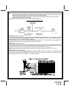
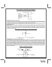
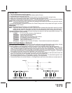
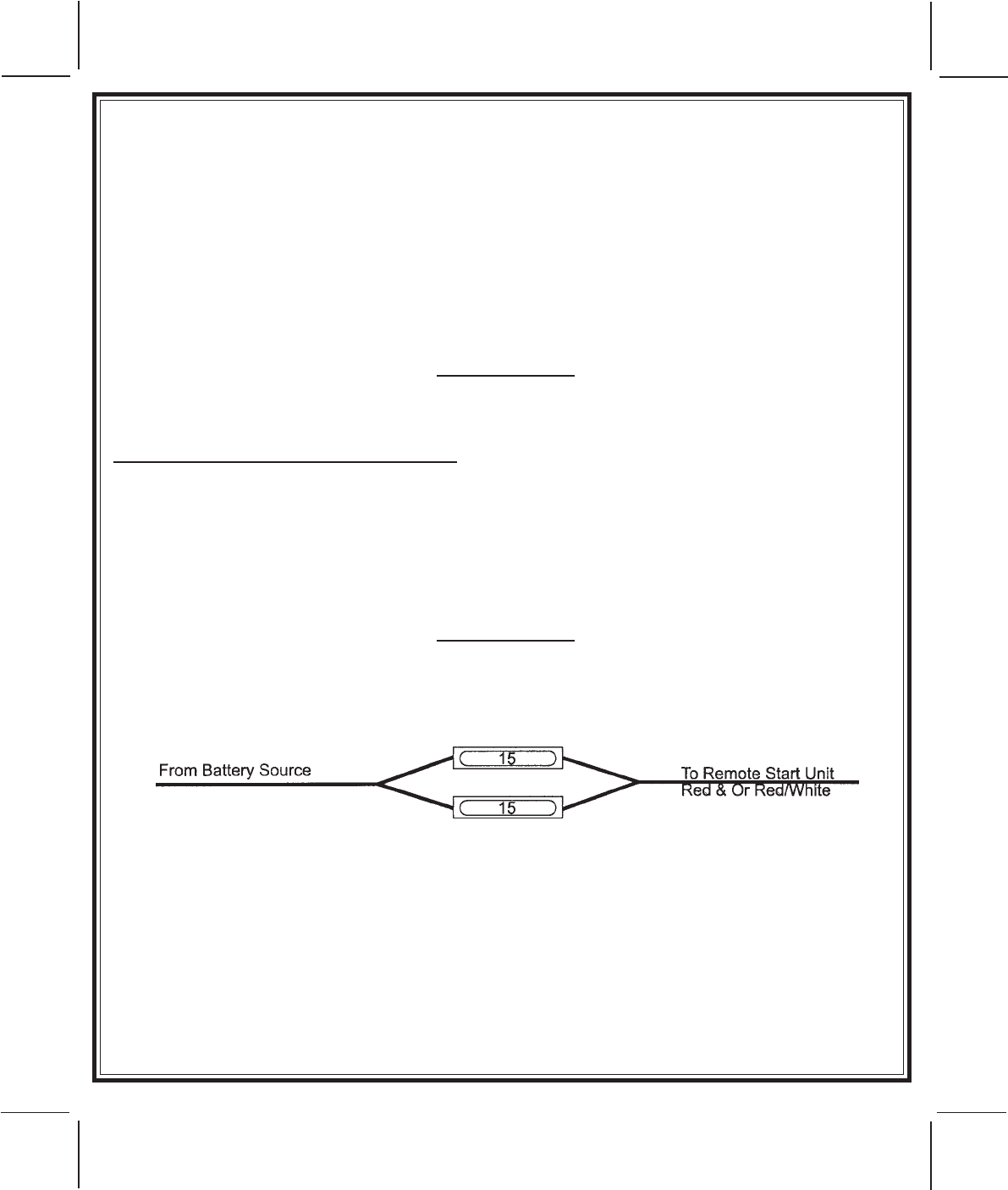
IT IS THE RESPONSIBILITY OF THE INSTALLING TECHNICIAN TO DETERMINE THE LOAD FACTOR OF
THE VEHICLE'S ELECTRICAL CIRCUITS WHEN THE VEHICLE IS RUNNING AND TO ADEQUATELY FUSE
THE TWO POWER WIRES BASED ON THAT LOAD. IF THE VEHICLE RUNNING UNDER LOAD WITH THE
AIR CONDITIONER, HEATER BLOWER MOTOR, AND ACCESSORIES EXCEEDS 24 AMPS CONTINU-
OUS, WE RECOMMEND THAT TWO FUSES BE USED IN COMBINATION ON EACH POWER WIRE AS
SHOWN BELOW. FOR ADDITIONAL INFORMATION, SEE TECH UPDATE ISSUED 9/30/96.
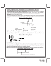
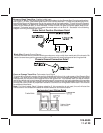
YELLOW WIRE: Starter Output
Careful consideration for the connection of this wire must be made to prevent the vehicle from
starting while in gear. Understanding the difference between a mechanical and an electrical Neu-
tral Start Switch will allow you to properly identify the circuit and select the correct installation
method. In addition you will realize why the connection of the safety wire is required for all me-
chanical switch configurations.
Failure to make this connection properly can result in personal injury and property damage. In all installations
it is the responsibility of the installing technician to test the remote start unit and assure that the vehicle
cannot start via RF control in any gear selection other than park or neutral.
In both mechanical and electrical neutral start switch configurations, the connection of the Yellow wire will be
made to the low current start solenoid wire of the ignition switch harness. This wire will have +12 volts when
the ignition switch is turned to the start (crank) position only. This wire will have 0 volts in all other ignition
switch positions.