


128-8605
5 of 20
5
This Remote Start/Alarm System is designed to be used with Automatic Transmission Vehicles Only!
The unit provides a selectable ignition control that allows a number of selectable timed outputs for glow plug
pre-heat which may be required for certain diesel vehicles, (see selectable feature #9). If the diesel engine has
a instant fire, (no glow plug pre-heat system), feature #9 should remain in the default Gasoline mode setting.
For diesel applications, consult your dealer for the type of ignition system used in your particular vehicle.
Regardless of the vehicle, Gasoline or Diesel, for every installation, the vehicle MUST HAVE a Tach Signal
Input, and an Automatic Transmission.
INSTALLATION OF THE MAJOR COMPONENTS:
CONTROL MODULE:
Select a mounting location inside the passenger compartment (up behind the dashboard). The mounting
location selected must be within 24" of the ignition switch wiring harness to allow connection of the 6 pin main
wiring harness.
Be certain that the chosen location will not interfere with proper operation of the vehicle. Avoid mounting the
module to or routing the wiring around the steering shaft/column, as the module or wiring may wrap around or
block the steering wheel preventing proper control of the vehicle. Secure the module in the chosen location
using cable ties or screws as necessary.
Do not mount the module in the engine compartment, as it is not waterproof.
OPTIONAL SIREN:
Select a location in the engine compartment that is not accessible from below the vehicle. The selected
location must be clear of hot or moving parts within the engine compartment. The siren must be pointed
downward to prevent water retention and the flared end must be pointed away from and out of the engine
compartment for maximum sound distribution. Before securing the siren, check behind your chosen location
to assure that the mounting screws will not penetrate any factory wiring or fluid lines. Secure the siren
mounting bracket using #8 self taping screws or by first using the mounting bracket as a template, scribe or
mark the mounting holes. Drill the marked holes using a 1/8" drill bit, then mount the siren using #8 sheet
metal screws.
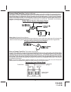
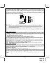
HOOD AND OPTIONAL TRUNK PIN SWITCHES:
The pin switch included in this package is intended for protecting the hood area of the vehicle. In all cases, the
switch must be mounted to a grounded metal surface. When the pin switch is activated, (hood open), it will
supply a ground to the input wire activating the alarm. In addition, the hood switch is required for the safety
shut down of the remote start unit. If the vehicle is being worked on, this hood switch prevents the remote start
activation even if the RF command to start is issued. This switch must be installed in all applications.
Failure to do so may result in personal injury or property damage. Mount the switch in the hood
locations away from water drain paths. If necessary, the use of an L bracket may be used to move the switch
away from rain gutters or allow mounting to the firewall behind the hood seal. In both cases the switch must
be set up to allow the hood to depress the switch at least 1/4 inch when the hood closed, and fully extended
when the hood is opened. For direct mounting, a 1/4 inch hole must be drilled. Carefully check behind the
chosen location to insure the drill will not penetrate any existing factory wiring or fluid lines.
Drill a 1/4" hole in the desired location and thread the pin switch into it using a 7/16" nut driver or deep well
socket. If using the mounting bracket, first secure the bracket to the desired location and secure the pin
switch in the pre-threaded mounting bracket hole.
For Trunk areas a similar installation method may be used and an optional switch may be purchased from the
Audiovox Accessory Catalog.
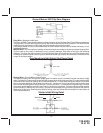
THE RECEIVER/ANTENNA /PUSHBUTTON/LED ASSEMBLY:
The Superheterodyne Receiver Antenna Assembly provided with this unit allows routing from below the dash
board for maximum operating range. Choose a location above the belt line (dashboard) of the vehicle for best
reception. Special considerations must be made for windshield glass as some newer vehicles utilize a metal-
lic shielded window glass that will inhibit or restrict RF reception. In these vehicles, route the antenna toward
a rear window location for best reception. Secure the antenna with double stick tape provided. After securing
the antenna with tape, we advise also securing a section of the antenna cable to a fixed support. This will
prevent the antenna from dropping down in case the double stick tape is exposed to extreme heat which may
loosen its gummed surface. Route the 3 connectors toward the control module and plug the single blue wire's
white connector into the mating LED connector on the module, plug the single grey wire's blue connector into
the mating valet/override connector on the module and plug the 3 wire RF connector into the mating connector
of the module. Use caution not to pinch the cable as this will cause poor or no RF reception no LED, or the
inability to program the unit.
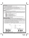
SHOCK SENSOR:
Select a centrally located, solid mounting surface for the shock sensor that will allow consistent operation