


128-8605
12 of 20
12
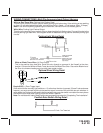
Green/Yellow Wire: Diesel Wait To Start Input
The Green/Yellow wire will connect to a diesel vehicles glow plug wire. When the unit receives a start command,
this wire must go to + 12 then to ground to allow the crank sequence to begin. When ignition #1 is activated by the
remote start unit, the glow plug circuit gets energized, (+ 12 volts), when the glow plug circuit of the vehicle drops
the + 12 volts, which effectively grounds the wait to start input, then 500mS later the starter will engage. This wire
can also be connected to the Glow Plug Bulb wire in the vehicle if this bulb wire gets + 12 volts when the ignition
comes on and drops low when the glow plug circuits temperature is reached. Be sure to fuse the wire with a 1 Amp
Fuse when connecting to a high current circuit such as a factory glow plug wire. The fuse should be installed as
close to the high current wire as possible. If you are installing this unit in a Gasoline vehicle, this wire is not used.
Note: If the Glow Plug sense wire, Green/Yellow is connected, this wire will have priority over the setting of feature
Bank 3 Feature #11.
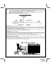
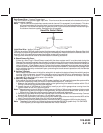
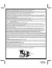
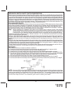
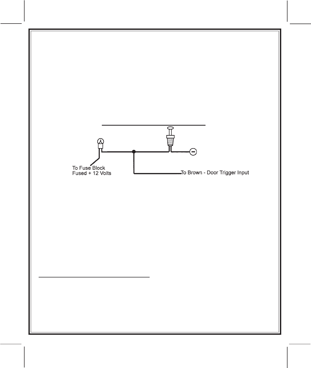
Brown Wire: Negative Door Trigger
If the vehicle's door courtesy light switches ground when the door is opened, (Most GMs and Imports), you
must connect this wire to the negative output from one of the vehicle's door pin switches. In most cases the
Brown wire will need to be connected to only one door switch no matter how many doors the vehicle has as
most door lighting circuits are wired in parallel.
NOTE: For vehicles with interior delay lighting see programming under title "Completing The Installation"
Negative Door Switch Wiring Detail
Dark Blue/Black Trace Wire: External Trigger Input
The Dark Blue/Black trace wire allows the remote start unit to be activated from an external source. The
intent of this wire is to allow the unit to be controlled from a "POSSE/CAR-LINK" paging system or similar
device. When this wire receives a ground pulse, the unit will start the vehicle. Connect this wire to a ground
pulsed output from the controlling circuit.
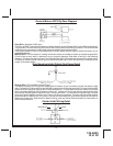
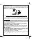
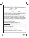
Black w/ White Trace Wire : 300 mA Horn Output
The black w/ white trace wire is provided to beep the vehicle’s horn. This is a transistorized low current
output, and should only be connected to the low current ground output from the vehicle’s horn switch.
If the vehicle uses a + 12 VDC horn switch, then connect the black w/ white trace wire to terminal 86 of the
AS 9256 relay ( or an equivalent 30 Amp automotive relay ), and connect relay terminal 85 to a fused + 12
VDC battery source. Connect relay terminal 87 to the vehicle’s horn switch output, and connect relay
terminal 30 to a fused + 12 VDC battery source.
YELLOW w/ BLACK Tracer Wire: + 12 Volt Alarm By - Pass Output
Note: You must disconnect the ignition input of the alarm from any other wire that it is presently connected
to in the vehicle.
This wire provides a + 12 Volt output when the ignition key is turned to the “ON” position, and 0 Volts when
the ignition key is “OFF” and when the vehicle is running under the control of the remote starter.
This wire should be connected to the ignition input of the alarm system.
The Yellow w/ Black wire output will allow you to remote start the vehicle while leaving the alarm armed, and
to lock/unlock the doors while running under control of the remote start unit.
UNDERSTANDING ARM & DISARM #1 AND #2:
Because of the complexities of the different factory installed Remote Keyless Entry Units on the market
today, this system uses two disarm and two arm inputs. Whether installing into a vehicle using a 2-step
unlock circuit, single step unlock circuit, or as a stand alone passive alarm, both disarm and arm wires must
be connected in all installations.
The arm and disarm functions of this system are learned during power up, by monitoring the resting state
of the factory wires when power is applied to the unit. Be certain all wires are connected to the vehicle before
applying power to the circuit to insure the system responds only during operation from the factory
transmitters.
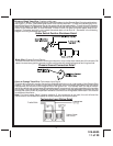
5 PIN WHITE CONNECTOR: GREEN/BLACK, RED, GREEN, RED/BLACK, & BLUE FACTORY
KEYLESS INPUTS: