


128-8605
14 of 20
14
output would be to disarm a factory theft deterrent system to prevent false triggering of the factory alarm when
the remote start unit engages or when the 785 is used to unlock the doors.
Black w/ Light Green Trace Wire: Pulsed Ground Output After Start
The Black w/ Light Green Trace wire will provide a 1 second mA pulsed ground output after the vehicle is
started under control of the remote start unit. Typically this wire will be used to re-lock the vehicle doors if the
doors unlock automatically when the factory anti-theft system is disarmed.
Black w/ Red Trace Wire: Pulsed Ground Output After Shutdown
The Black w/ Red Trace wire will provide a 1 second 300 mA pulsed ground output after the remote start unit
shuts down. This output will occur regardless of whether the circuit times out or is manually terminated.
Typically this output will be used to re-lock the vehicle doors if the doors unlock automatically when the
ignition circuit transitions to off.
Black w/ Yellow Trace Wire: Ground Output During Start (Crank)
The Black w/ Yellow Trace wire will provide a 300 mA ground output while the starter output of the remote start
unit is active. This output can be used to activate the Crank Low/Bulb Test wire found in some GM vehicles.
This wire is also referred to as the ECM wake up wire in some vehicles.
Note: The outputs above are low current outputs and must be used with a relay if the circuit's requirement
is more than 300mA.
2 Pin Transponder Control Output: (Yellow Connector)
This output is intended to allow the control of a transponder bypass interface module or transponder
bypass relay. The system also allows software selections to control the way in which this output operates,
see remote start feature # 10 for setting this output.
When the unit is selected for output during the start sequence, this output will be active at the same time
Ign. 3 becomes active, and will remain active until the vehicle has started. This will be used for one time
read transponder circuits.
When the unit is selected for transponder on, this output will become active at the same time ign. 3
becomes active, and will remain active all the time the unit is operational under the control of the remote
start. When the unit is selected for continuous and the vehicle is started via the Remote Start, this output
will become active at the same time ign. 3 becomes active and will remain active until the ignition in the
vehicle goes low. This will allow the unit to be used for continuous read transponders circuits.
Receiver Pushbutton LED/Valet/Program/Override Switch: (Blue, White & Black Connectors)
The Grey and the Blue wires loaded into individual 2 pin connectors, and the Black, Green & Red wires loaded
into the 3 pin black connector are the Valet enable, LED cathode, & the RF power ground and RX. When the
Grey wire is grounded, under certain conditions, the unit will enter the valet mode. When the Grey wire is
sequentially grounded under other conditions, the unit will enter the various program modes indicated on the
integral LED built into the receiver. Route the Blue, White and Black connectors from the Combination receiver
assembly to the remote start unit and plug these connectors into the mating blue, white, and black connec-
tors of the control module. For valet, remote start override, and alarm override information, refer to the owners
manual.
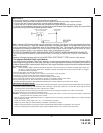
2 Pin Door Lock/Unlock Harness: (White Connector)
The Red and Green wires will provide either a pulsed ground output to the factory door lock control relay, or a
pulsed + 12 volt output to the factory door lock control relay. In either case, the maximum current draw through
these outputs must not exceed 300mA.
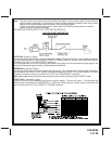
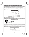
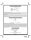
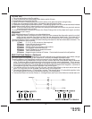
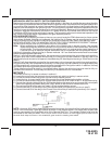
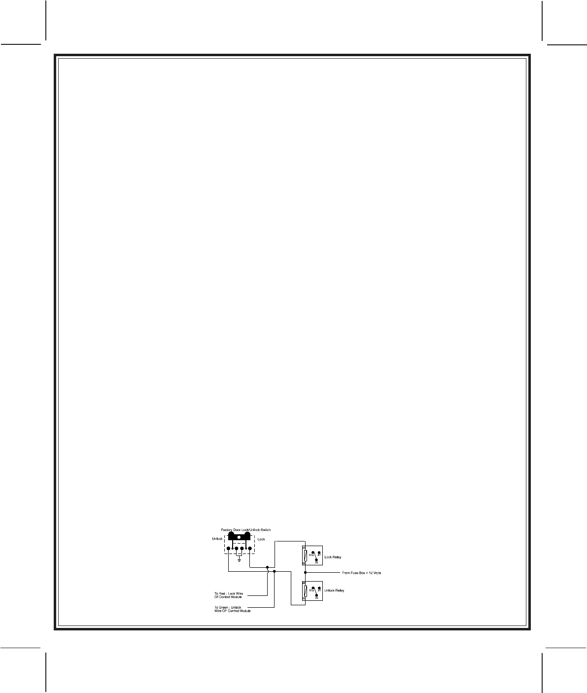
3 Wire Ground Switched Door Lock Circuits:
In this application, the Red wire of the door lock harness provides a ground pulse during the arming sequence,
or pulsed ground lock output. Connect the Red wire to the low current ground signal wire from the factory door
lock switch to the factory door lock relay.
The Green wire of the door lock harness provides a ground pulse during the disarming sequence, or pulsed
ground unlock output. Connect the Green wire to the low current ground signal wire from the factory door
unlock switch to the factory door unlock relay. See Below For Wiring Detail.