


AW Company 8809 Industrial Drive, Franksville, WI 53126 à web: www.awcompany.com
Tel: 262-884-9800 Fax: 262-884-9810 | Email: aw@awcompany.com
REV. 4 10/05 EMO-500 Manual.DOC
6
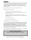
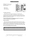
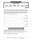
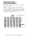
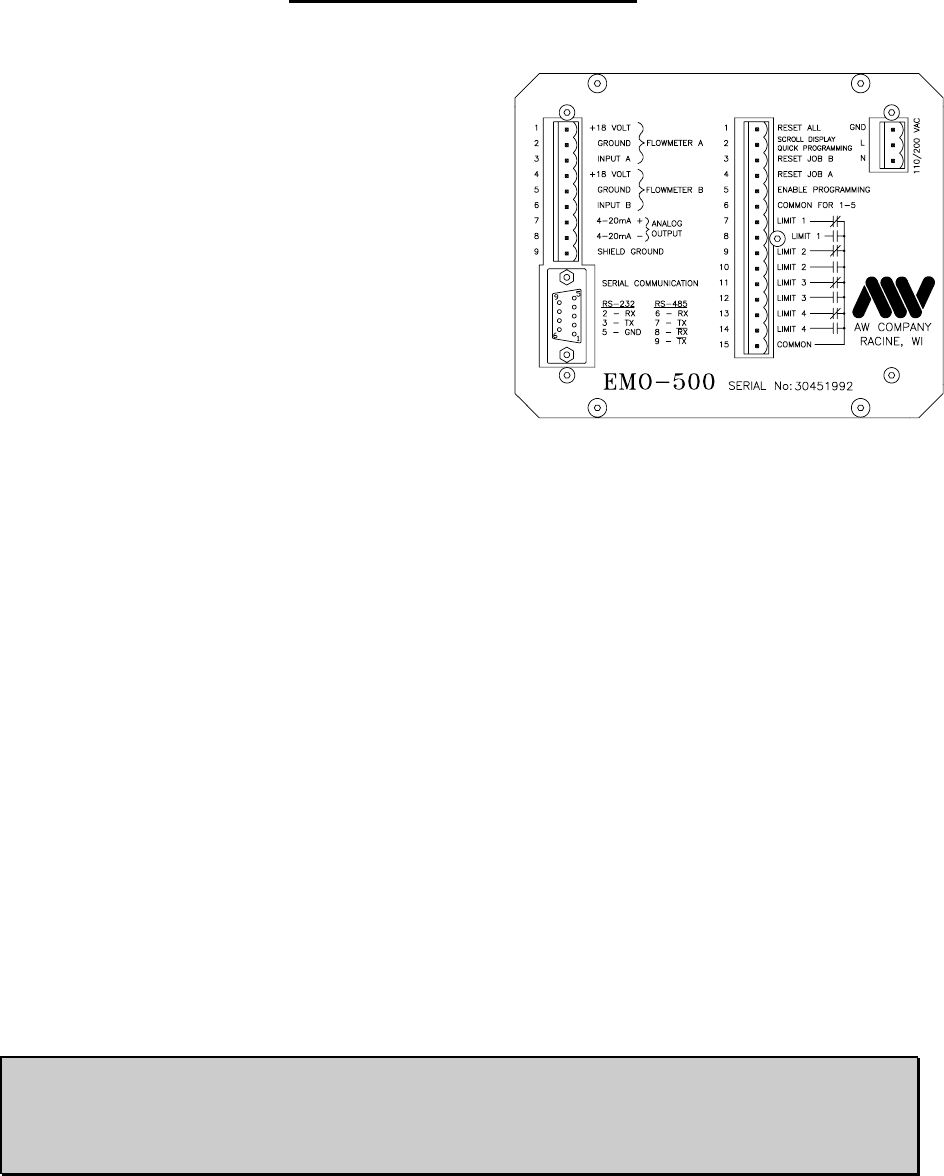
Hardware Connections
Warning: The AC Power should
be wired just as labeled on the
three pin connector
.
PIN 1-Ground
PIN 2-Line 110v.
PIN 3-Line Neutral
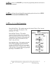
Grounding Considerations
The grounding is a most important consideration in an installation where
microprocessor technology is applied. The EMO-500 is a panel mounted unit and
therefore the casing is connected to the sub-panel. If the sub-panel is metal it should be
grounded. If the sub-panel is non-conductive - PIN 1 of the three pin connector on the
EMO-500 back panel must be grounded
.
To insure a proper ground we recommend connecting PIN 1 of the three pin
connector to the panel's central ground point.
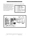
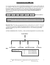
Signal and Shielding
The two flow meter pick-ups should be supplied with their respective 18v. supply
voltages and referenced to their respective grounds. This will insure that the input signals
from the flow meters are referenced to the ground connections on pins 2 and 5. Most
applications require some signal shielding. A solid aluminum wrap shielding will work
fine. The shield should be connected to pins 2 and 5 on the flow meter connector. DO
NOT connect the shielding at the flow transmitter.
IMPORTANT! NEVER CONNECT THE SHIELD TO GROUND AT BOTH ENDS!!
DOING SO CAN PRODUCE UNWANTED OSCILLATIONS IN THE SIGNAL WIRES.