


AW Company 8809 Industrial Drive, Franksville, WI 53126 à web: www.awcompany.com
Tel: 262-884-9800 Fax: 262-884-9810 | Email: aw@awcompany.com
REV. 4 10/05 EMO-500 Manual.DOC
5
Special Features of the EMO-500
The EMO 500 is especially suited for use in dispensing systems with irregular flow
patterns. The unit employs a user programmable sampling size to govern how often the
ratio display is updated - the operator then has maximum control over the sampling period
and can easily adjust this to suit his own system parameters. The user is often more
interested in the ratio of components dispensed over a period of time, say in a batch,
rather than on an instantaneous basis.
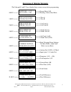
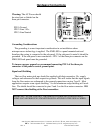
Programming
< There are 3 methods of programming the unit - two have lockout features to
prevent unauthorized access.
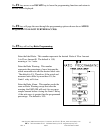
Full Programming Enable:
< The full programming menu is accessible by placing a jumper between pin 5
(enable programming) and pin 6 (Common). The F2 key will page through the
menu of programming options - these options are indicated in red lettering on a
banner above the upper function keys.* See Programming the EMO 500 (Pg.8).
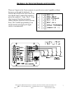
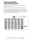
Quick Programming Feature:
< Some variables only need to be installed once. With others, such as Gate Time or
Sample Time, the user may wish to experiment to find a preferred value. To make
this easier or make some selected variables permanently available, such selected
programming functions are accessible in the following way:
Simultaneously - Engage the 'Scroll Display' (jump pin #2 to #6) and press one key on the
upper line, F1 through key #1. Note -The variable is highlighted in red on the key. Press
Enter (F6) to exit. (Pg.17).
Serial Port Programming:
< The EMO-500 is fully programmable through the serial port using RS-232 or
RS-485 type communication. Refer to the Serial Port Operations portion of this
manual for complete information.
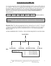
Sample Size - # of impulses collected for the Ratio Calculation.
< To determine the ratio - the total number of pulses from both flow meters are
separately counted until one of them reaches the programmed Sample Size. The
number of pulses from flow meter A is then divided by the number of pulses from
flow meter B. The governor will therefore be the meter with the slower pulse rate.
The Sample Size determines both the accuracy and response time of the ratio
calculation - reducing the sample size, increases the response time but decreases
the accuracy. A default value of 200 is factory installed. See P.
Gate Time - Time period over which Rate Calculations are made.
< The gate time (in seconds) is the time period the microprocessor collects pulses to
perform rate calculations. A default value of 1.85 is factory installed. See P.15.