


AW Company 8809 Industrial Drive, Franksville, WI 53126 à web: www.awcompany.com
Tel: 262-884-9800 Fax: 262-884-9810 | Email: aw@awcompany.com
REV. 4 10/05 EMO-500 Manual.DOC
21
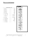
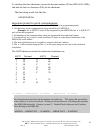
8. Gate Time ........................................................................................... Default 1.85 sec.
The gate time (in seconds) is the amount of time pulses are accepted before flow rate
calculations are performed. The accuracy and response time of the flow rate display are
dependent on the gate time. To achieve a 1% flow rate accuracy, the lowest pulse rate
should produce 100 pulses before the rate calculation is performed. In display #7 (Status
Display 2) the lower line indicates incoming flow meter impulses, an estimate of the time
elapsed for 100 pulses, to be accumulated by the slowest meter, will give a good
approximation of the minimum recommended gate time.
Another method would be to change the default Gate Time value by trial and error
until the best results for the system and user are achieved.
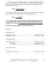
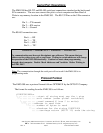
9. Analog Offset.............................................................................................Default 0000
The Analog Output Offset will be a number from 0000-4095 that will become the
bottom end of the 0 - 5 volt & 4 - 20 mAmp analog outputs.
For example: 0000 for 0 to 20mAmps and 0 to 5v.
819 for 4 to 20mAmps and 1 to 5v.
1638 for 8 to 20mAmps and 2 to 5v.
2457 for 12 to 20mAmps and 3 to 5v.
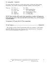
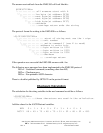
10. Analog Gain............................................................................................Default 10200
The analog gain factor integrates the controller output signal range and speed with the
rest of the system capabilities. If the gain factor is correct the full range of the analog
output signal can be used to cover the operating range of the equipment in which it is
installed.
The formula used to determine the analog output is as follows:
(Variable Value) * Gain
Analog Output=
512