STARTING AND OPERATING THE VEHICLE AIR SUSPENSION HEIGHT/AIR PRESSURE
Regional Haul
(R05/10) Y53-6033 – 133 –
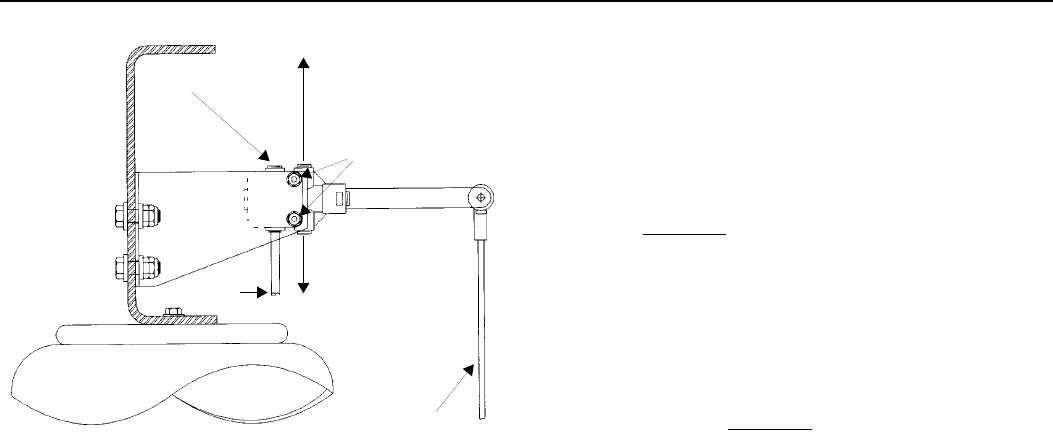
Typical Height Control Valve
(Rear View Looking Forward)
3. Rotate the valve either clockwise or counterclockwise
until air pressure in the air springs provides the ride
height specified for that suspension. Measure the ride
height from the bottom of the frame rail to the approx-
imate centerline of the rearmost drive axle hub:
• For tandem axles, make the vertical measurement
at the centerline of the suspension (see illustration
on
page 131).
• For a single axle, make the measurement in front of
the axle, in the area forward of the tires but not past
the suspension bracket.
4. When at the correct ride height, ensure that the height
control valve lever is in the neutral position, then
install either the built-in alignment pin or a 1/8-inch (3
mm) dowel (see page 131
).
5. Torque the mounting fasteners to 55 — 75 lb. in.
(6.2 — 8.5 N.m.).
6. Remove the alignment pin or dowel.
7. Repeat Steps 2 through 6 above for the RH valve on
vehicles with a dual-valve system.
SUPPLY FROM FORWARD
AIR TANK
DELIVERY TO RH AIR BAG(S)
DELIVERY TO LH AIR BAG(S)
MOUNTING NUTS
AIR BAG
LINK ROD
EXHAUST
02941B


