EPSON Stylus Color 900 Revision c
Appendix Connector Summary 172
7.1 Connector Summary
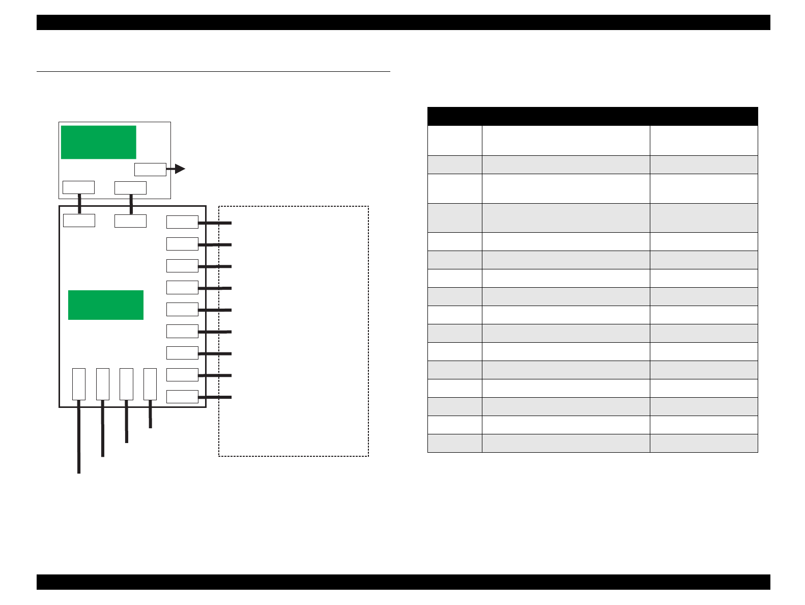
Figure 7-1 shows the cable connection of the Stylus Color 900.
Figure 7-1. Cable Connection of the Stylus Color 900
Table shows the connector assignment of the C265 Main Board.
Table 7-1. C265 Main Board Connections
C265PSB/PSE
(Power Supply
Board)
CN1
AC
CN2
CN5
CN3
CN8
C265MAIN
(M ain Board)
CN1
CN2
CN10
CN11
CN4
P F M o to r d riv e
ASF Sensor
PE Sensor
P a ra lle l I/F
Type-B I/F
M a c . S e ria l I/F
USB I/F
CN15
CN3
CN6
CN9
CN12
CN13
CN14
CN16
B k , M , C n o z z le d riv e
Y e lo w n o z z le d riv e
HP Sensor
C ontrol Panel
C R M o to r d riv e
ASF Motor drive
C ooling Fan drive
Therm istor on the heat sink
ASF Solenoid drive
Logic
Line
Power
Line
Connector Function Refer to:
CN1 Parallel I/F connector
Chapter 1 / Interface
specifications
CN2 Type-B I/F connector Type-B I/F Manual
CN3 Mac. Serial I/F connector
Chapter 1 / Interface
specifications
CN4 USB I/F connector
Chapter 1 / Interface
specifications
CN5 Power supply (Logic line) Table 7-2
CN6 Power supply (Power line) Table 7-3
CN7 ---- ----
CN8 Bk, Magenta, Cyan nozzle drive Table 7-4
CN9 Yellow nozzle drive Table 7-5
CN10 PF motor drive Table 7-6
CN11 CR motor drive Table 7-7
CN12 ASF motor drive Table 7-8
CN13 Cooling fan drive Table 7-9
CN14 Thermistor on the heat sink Table 7-10
CN15 Panel and Sensors (HP, PE, ASF) Table 7-11
CN16 ASF solenoid drive Table 7-12


