


11
18
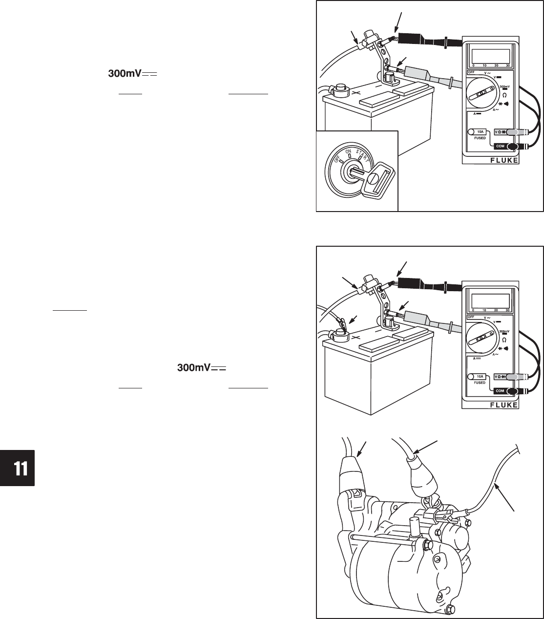
STARTER SYSTEM
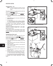
Testing Starter – All
NOTE: To prevent engine from starting, remove
fuel shut off solenoid wire from injector
pump.
The starter current draw test will be performed with the
meter in the position.
The DC Shunt must be installed on the negative (-)
terminal of the battery, Fig. 48.
1. Attach RED meter test lead to RED post terminal
on shunt.
2. Attach BLACK meter test lead to BLACK post
terminal on shunt.
3. Activate starter.
a. Allow 3 seconds for meter reading to stabilize.
4. Current draw should not exceed 140 amps DC.
If amperage draw exceeds specification, remove
starter from engine and perform No Load starter
current draw test.
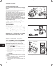
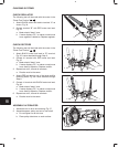
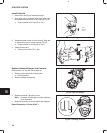
Fig. 48 – Starter Current Draw Test
NEGATIVE
BATTERY
CABLE
BLACK
LEAD
RED
LEAD
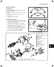
STARTER CURRENT DRAW TEST – NO LOAD
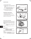
Remove starter motor.
To hold starter securely while testing, clamp starter
mounting bracket in a vise. DO NOT clamp starter
housing in a vise or field windings or magnets may be
damaged.
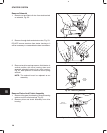
Testing Starter (No Load)
The No Load starter current draw test will be per-
formed with the meter in the position.
The DC Shunt must be installed on the negative (-)
terminal of the battery, Fig. 49.
1. Attach RED meter test lead to RED post terminal
on shunt.
2. Attach BLACK meter test lead to BLACK post
terminal on shunt.
3. Attach negative battery cable to a good ground
such as drive housing.
4. Attach positive battery cable to battery terminal on
solenoid.
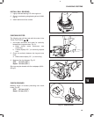
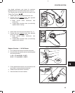
5. Attach one end of jumper wire to solenoid tab
terminal, Fig. 49.
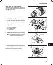
6. Activate starter by contacting positive battery
terminal with other end of jumper wire, Fig. 49.
a. Allow 3 seconds for meter reading to stabilize.
7. Current draw should not exceed 90 amps DC.
If amperage draw exceeds specification, replace
starter.
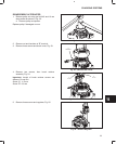
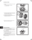
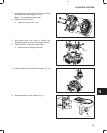
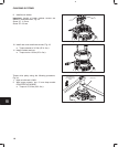
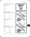
Fig. 49 – No Load Starter Current Draw Test
JUMPER
WIRE
NEGATIVE
CABLE
BLACK
LEAD
RED
LEAD
NEGATIVE
CABLE
JUMPER
WIRE
POSITIVE
CABLE