


11
13
CHARGING SYSTEMS
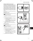
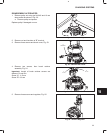
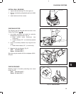
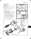
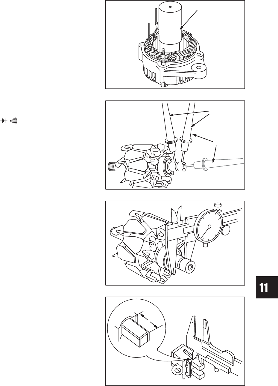
INSTALL BALL BEARING
1. Lightly lubricate bearing O.D. with engine oil.
2. Press in new bearing using bearing driver #19226,
Fig. 30.
3. Install retainer and four screws.
Fig. 30 – Install Ball Bearing
19226 DRIVER
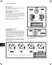
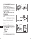
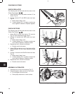
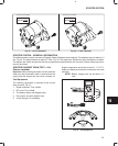
CHECKING ROTOR
The following test will be made with the meter in the
“Diode Test Position” .
1. Use digital multimeter and check for continuity
between slip rings as shown, Fig. 31.
a. Meter should make continuous tone
(continuity).
b. If meter displays “OL”, (no continuity) replace
rotor.
2. Check for continuity between slip ring and rotor
shaft.
a. Meter should display “OL”, (no continuity).
Fig. 31 – Check Rotor
1
2
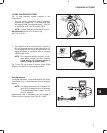
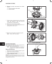
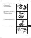
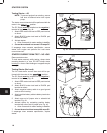
3. Measure slip ring diameter, Fig. 32.
STD: 14.4 mm (.567”)
Reject: 14.0 mm (.551”)
Slip rings may be cleaned with fine sandpaper (#300 –
500 grit).
Fig. 32 – Check Slip Ring
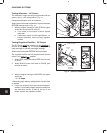
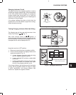
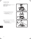
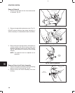
CHECK BRUSHES
Measure length of brushes protruding from brush
holder, Fig. 33.
STD: 10.5 mm (.413”)
Reject: 8.0 mm (.315”)
Fig. 33 – Check Brushes