


9
4
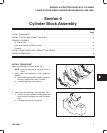
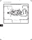
CYLINDER BLOCK ASSEMBLY
INSTALL TIMING GEAR CASE, CAMSHAFT
AND GEARS
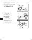
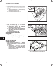
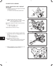
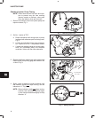
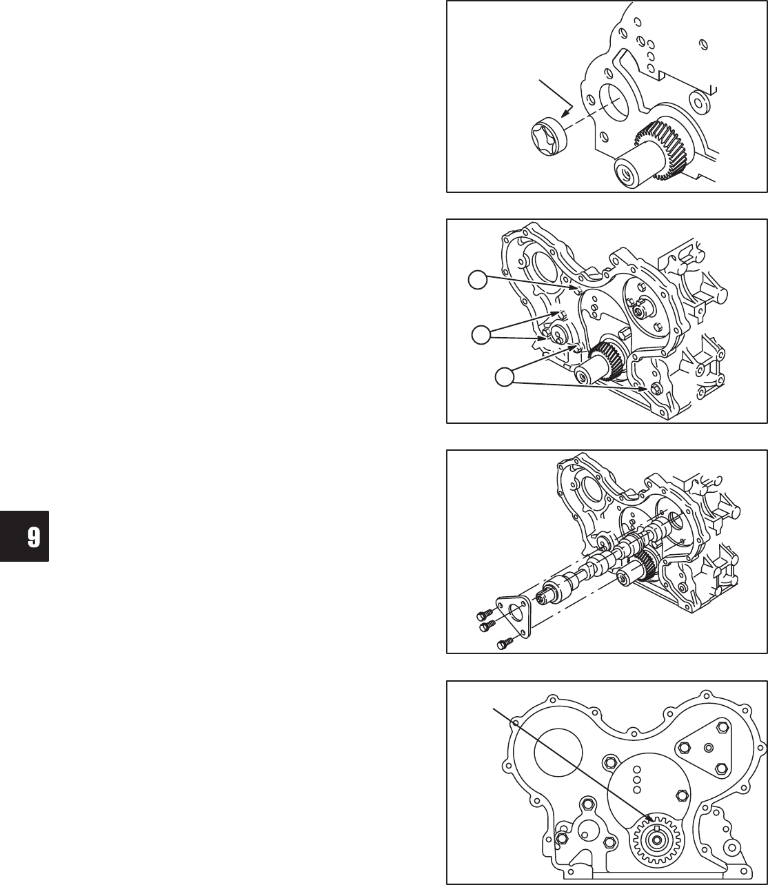
1. Lubricate oil pump rotor with engine oil and install
in cylinder block, Fig. 10.
a. ID mark on rotor must face cylinder block.
Fig. 10 – Installing Oil Pump Rotor
OIL PUMP
ROTOR
ID MARK
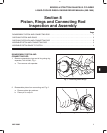
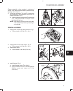
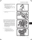
2. Install timing gear case with new gasket.
NOTE: It may be necessary to rotate oil pump
drive to engage oil pump rotors.
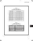
Note position, length and number of screws as shown,
Fig. 11.
a. M6 x 28 mm (M6 x 1.1”): 4
b. M6 x 16 mm (M6 x .6”): 1
Torque screws to 8.0 Nm (70 in. lbs.).
Fig. 11 – Installing Gear Case
B
A
A
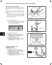
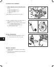
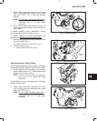
3. Lubricate, then install camshaft in cylinder block,
Fig. 12. Take care not to damage lobes or cam
bearing.
a. Install camshaft retainer.
b. M6 x 18 mm (M6 x 0.7”): 3
Torque screws to 8.0 Nm (70 in. lbs.).
NOTE: Position camshaft retainer so that center
hole does not interfere with camshaft.
Fig. 12 – Installing Camshaft
RETAINER
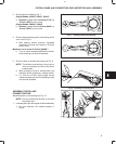
4. Rotate crankshaft so that crankshaft key is at
12 o’clock position as shown in Fig. 13.
Fig. 13 – Rotate Crankshaft
CRANKSHAFT
KEY 12 O’CLOCK