


11
14
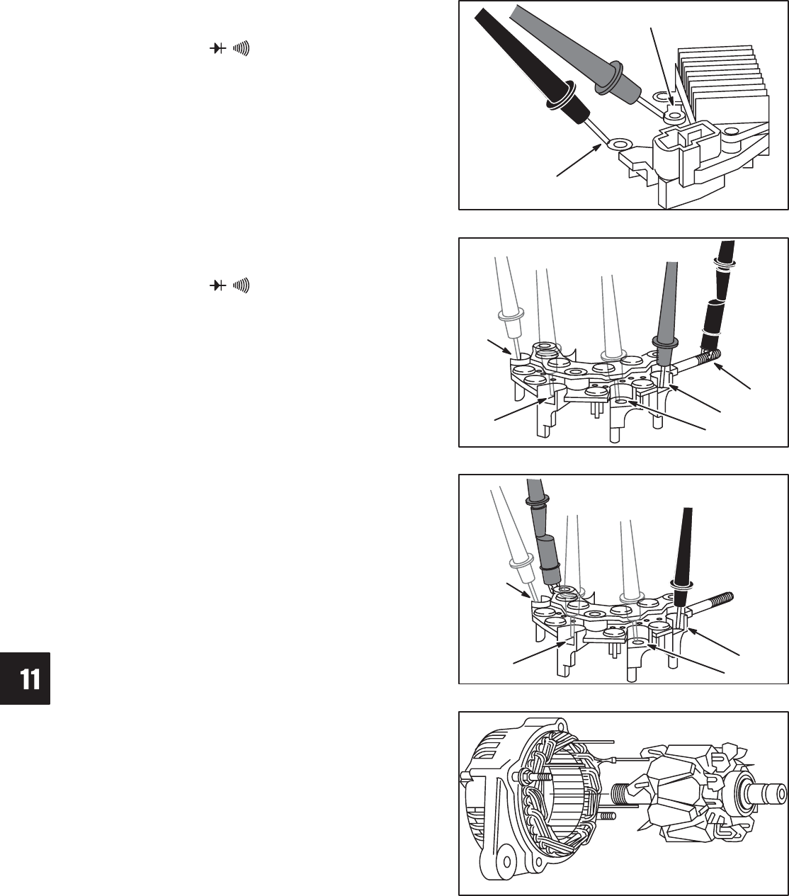
CHARGING SYSTEMS
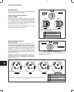
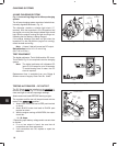
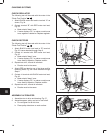
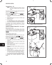
CHECK REGULATOR
The following test will be made with the meter in the
“Diode Test Position” .
1. Attach BLACK meter test lead to terminal “A” as
shown, Fig. 34.
2. Contact terminal “B” with RED meter test lead,
Fig. 34.
a. Meter should “beep” once.
b. If meter displays “OL” or makes a continuous
tone, regulator is defective. Replace regulator.
Fig. 34 – Check Regulator
B
A
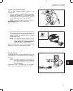
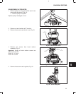
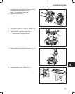
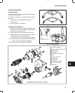
CHECK RECTIFIER
The following test will be made with the meter in the
“Diode Test Position” .
1. Attach BLACK meter test lead to “B” terminal,
Fig. 35. Leave attached through Step 3.
2. Contact #1 terminal with RED meter test lead,
Fig. 35.
a. Meter should “beep” once.
b. If meter displays “OL” or makes a continuous
tone, diode is defective. Replace rectifier.
3. Repeat test at #2, #3 and #4 terminals.
a. Results must be the same. Fig. 35 – Check Rectifier
#4
#3
#2
#1
B
TERMINAL
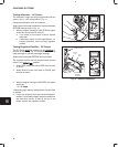
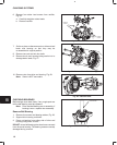
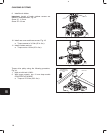
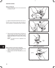
4. Attach RED test lead to one of the three rectifier
mounting holes, Fig. 36. Leave attached through
Step 6.
5. Contact #1 terminal with BLACK meter test lead,
Fig. 36.
a. Meter should “beep” once.
b. If meter displays “OL” or makes a continuous
tone, diode is defective. Replace rectifier.
6. Repeat test at #2, #3 and #4 terminals.
a. Results must be the same.
Fig. 36 – Check Rectifier
#4
#3
#2
#1
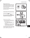
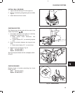
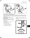
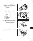
ASSEMBLE ALTERNATOR
1. Assemble rotor to drive end housing, Fig. 37.
2. Assemble spacer, pulley and nut to rotor shaft.
a. Do not tighten nut at this time.
b. Place pulley side down on work surface.
Fig. 37 – Installing Rotor