


11
9
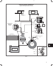
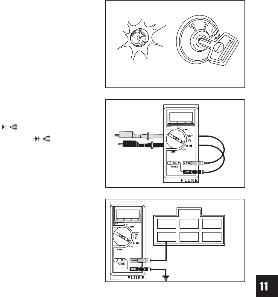
CHARGING SYSTEMS
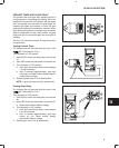
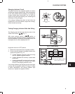
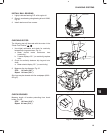
Charging Indicator Circuit
The green wire from the regulator-rectifier is used to
activate the charging indicator light. With the keyswitch
in the “ON” position and the engine not running the
charge indicator light should light, Fig. 16. With the
engine running the light should go out, indicating that
the battery is being charged.
If the charge indicator light does not light when the
keyswitch is in the “ON” position (engine not running),
check the bulb and wiring.
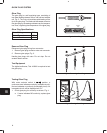
Fig. 16 – Charge Indicator Light
CHARGE INDICATOR
LIGHT
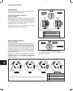
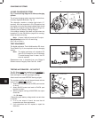
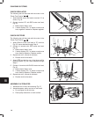
Testing Charging Indicator Bulb And Wiring
The following test will be made with the meter in the
“Diode Test Position” , Fig. 17.
With meter selector switch in position, a
continuous tone indicates continuity (complete circuit).
No tone indicates no continuity (incomplete circuit). An
incomplete circuit will be displayed as “OL.”
Fig. 17 – Meter Setting
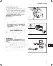
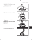
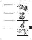
Keyswitch must be in OFF position.
1. Disconnect output harness at regulator-rectifier.
2. Check continuity between charging indicator wire
(green) and ground, Fig. 18.
a. If meter indicates continuity, bulb and wiring
are OK. Replace regulator-rectifier.
b. If meter indicates NO continuity, replace bulb
and re-test.
c. If meter indicates NO continuity with new bulb,
the problem must be a broken wire (open
circuit) in the charging indicator circuit.
If the charge indicator light remains on with the engine
running, test the regulator-rectifier DC output. If output
is within specification and charge indicator light
remains on, replace the regulator-rectifier.
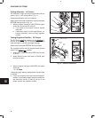
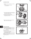
Fig. 18 – Testing Bulb And Wiring
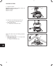
HARNESS CONNECTOR
WIRE COLOR AND TERMINAL POSITION
GREEN-CHARGE LAMP WIRE
LIGHT
BLUE
GREEN YELLOW
BLACK
RED
LIGHT
BLUE