


11
7
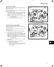
CHARGING SYSTEMS
14 AMP CHARGING SYSTEM
The 14 amp charging system consists of two
components:
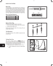
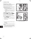
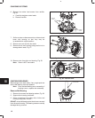
1. The belt driven permanent magnet alternator
produces AC voltage, Fig. 11. AC output will vary
with engine RPM, from approximately 7 volts AC
at 1000 RPM to 32 volts AC at 3000 RPM.
NOTE: A loose V-belt will cause low AC output.
Belt deflection limit is 9.5-11.5 mm/10 kg.
(3/8-7/16 in./22 lb.).
Fig. 11 – 14 Amp Alternator
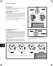
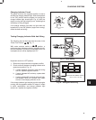
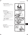
2. The regulator-rectifier converts the AC current to
DC and regulates current to the battery, Fig. 12.
The charging rate will vary with engine RPM. The
regulator-rectifier is equipped with a charging
indicator light circuit.
NOTE: The regulator-rectifier requires a mini-
mum battery voltage of 6 volts to function.
There will be no charging output if
battery voltage is below 6 volts.
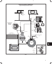
Fig. 78 and Fig. 80 at end of section, show wiring
diagrams for typical 14 amp charging system.
Fig. 12 – Regulator-rectifier
CHARGE INDICATOR
LIGHT
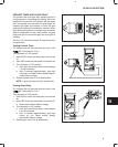
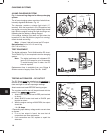
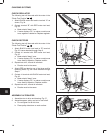
Test Equipment
The digital multimeter, Tool #19464 and the DC shunt,
Tool #19468, Fig. 13, are required to test the charging
system.
NOTE: The digital multimeter will withstand DC
input of 10-20 amps for up to 30 seconds.
To avoid blowing fuse in meter, the DC
shunt is required.
Replacement fuse is available from your Briggs &
Stratton source of supply. Order Part No. 19449.
Fig. 13 – Test Equipment
19464
19468