


10
6
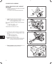
INJECTOR PUMP
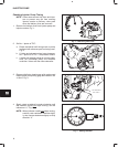
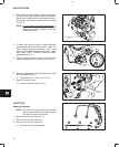
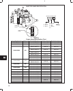
3. While observing dial indicator, slowly rotate injec-
tor pump away from cylinder head until indicator
shows correct specification. Hold injector pump in
this position and tighten outside pump mounting
nut, Fig. 9.
NOTE: Do not rotate pump past specification. If
pump is rotated past specification, rotate
pump back toward cylinder head and
repeat procedure.
Fig. 9 – Adjusting Timing
OUTSIDE MOUNTING
NUT
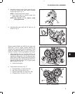
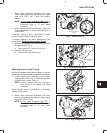
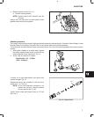
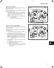
4. To verify that timing is correct, rotate crankshaft
counter-clockwise until dial indicator reads ‘‘0.”
Then rotate crankshaft clockwise until timing
mark on pulley aligns with reference point on gear
case cover (TDC). Indicator should be within
specification, Fig. 10.
5. Torque injector pump mounting nuts and pump
support bracket screw to 19.0 Nm (170 in. lbs.).
Fig. 10 – Verify Timing
METRIC INDICATOR
SHOWN
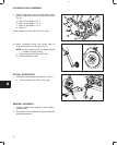
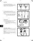
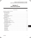
6. Remove timing gage and install distributor screw
with new washer, Fig. 11.
a. Torque screw to 17.0 Nm (150 in. lbs.).
7. Install fuel delivery lines.
a. Torque to 25.0 Nm (220 in. lbs.).
Fig. 11 – Installing Distributor Screw
DISTRIBUTOR
SCREW
INJECTORS
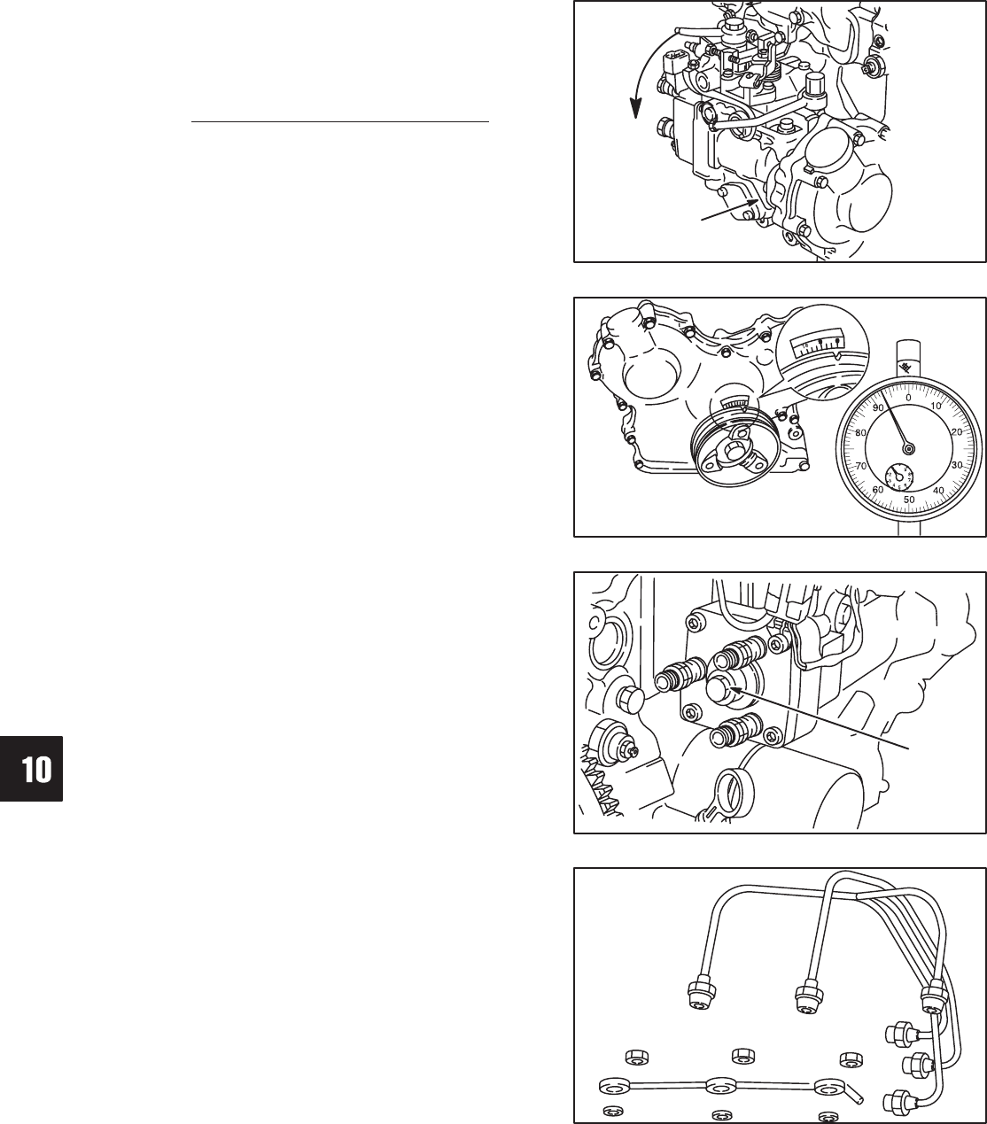
Remove Injectors
NOTE: Use care to prevent any dirt from entering
injector holes or delivery valve ports when
fuel delivery lines are removed.
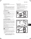
1. Remove fuel delivery lines, Fig. 12.
2. Disconnect fuel return line hose.
3. Remove nuts and fuel return line.
a. Discard fuel return line gaskets.
Fig. 12 – Removing Fuel Lines